Rotary electric machine and a rotor of the same

Active Publication Date: 2005-02-24
DENSO CORP
View PDF3 Cites 98 Cited by
  • Summary
  • Abstract
  • Description
  • Claims
  • Application Information

AI Technical Summary

Benefits of technology

[0023] In the distributed winding-type starter, demagnetization occurs less than a concentrated winding-type stator in which windings are wound many times to maintain a sufficient electro motive force, so a large armature reaction is generated when an armature current occurs. Therefore, in the Halbach array rotor, which requires a consideration of demagnetization, reliability to the demagnetization is improved. In the concentrated windi

Problems solved by technology

First, because the main pole magnets and the yoke magnets are opposed to one another, the magnets cause demagnetization between them.
As a result, they are likely to cause self-demagnetization.
In a case of motor, it is difficult to supply a large amount of current.
That is, load tolerance of the motor is low.
Therefore, if magnetic characteristic is reduced under a high temperature condition, the magnets are likely to be irreversibly demagnetized.
Accordingly, the rotor is easily affected by heat.
It is difficult to provide a high performance rotor with a compact body.
Next, because the main pole magnets and y

Method used


Image

  • Rotary electric machine and a rotor of the same
  • Rotary electric machine and a rotor of the same
  • Rotary electric machine and a rotor of the same

Examples


first embodiment

[0033] (First Embodiment)

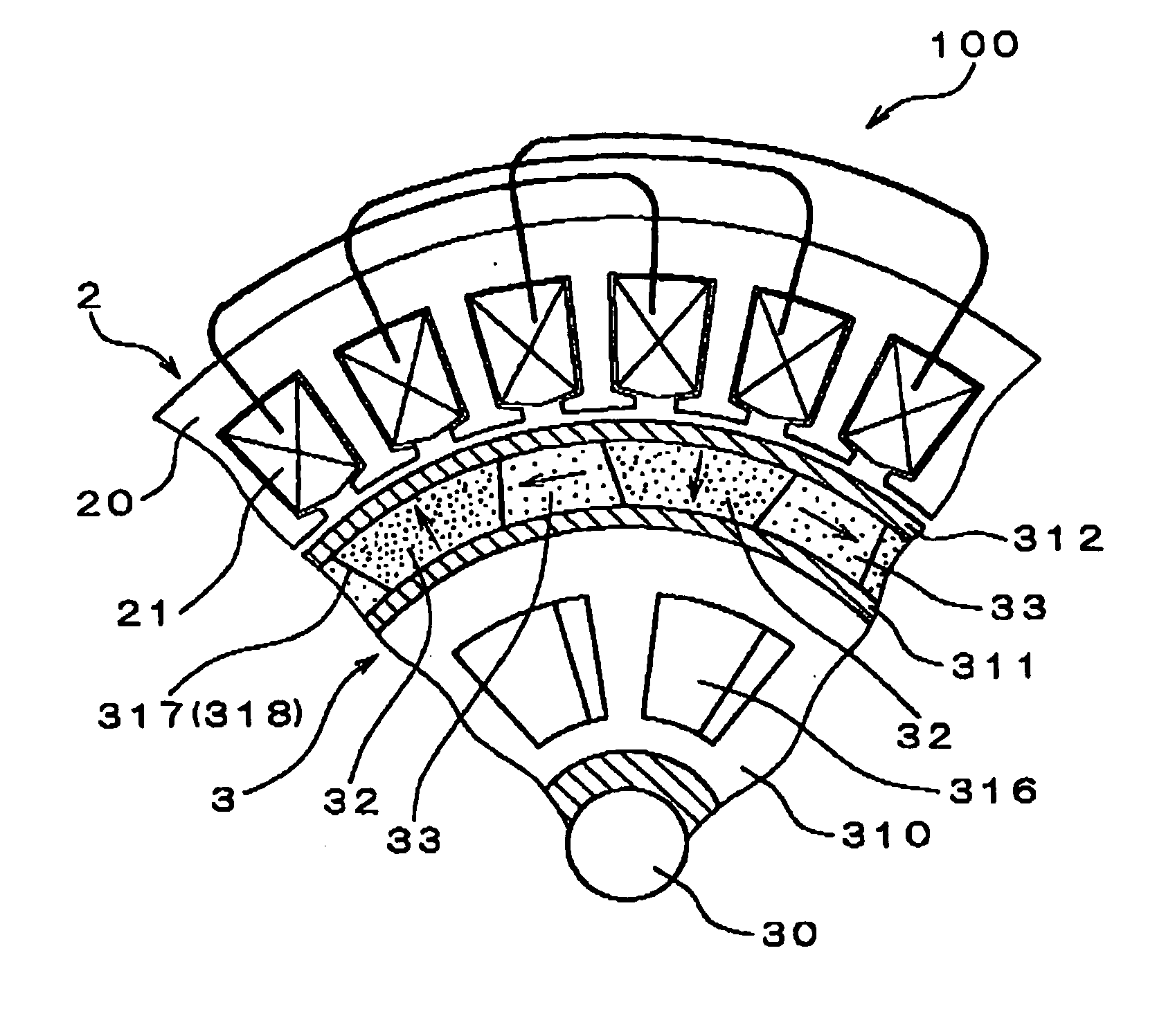
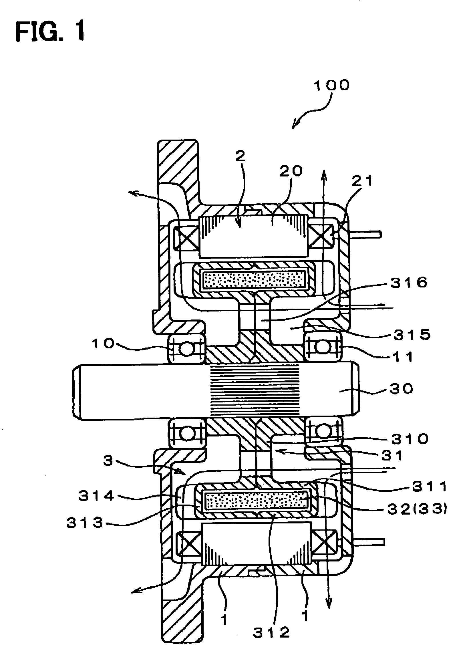
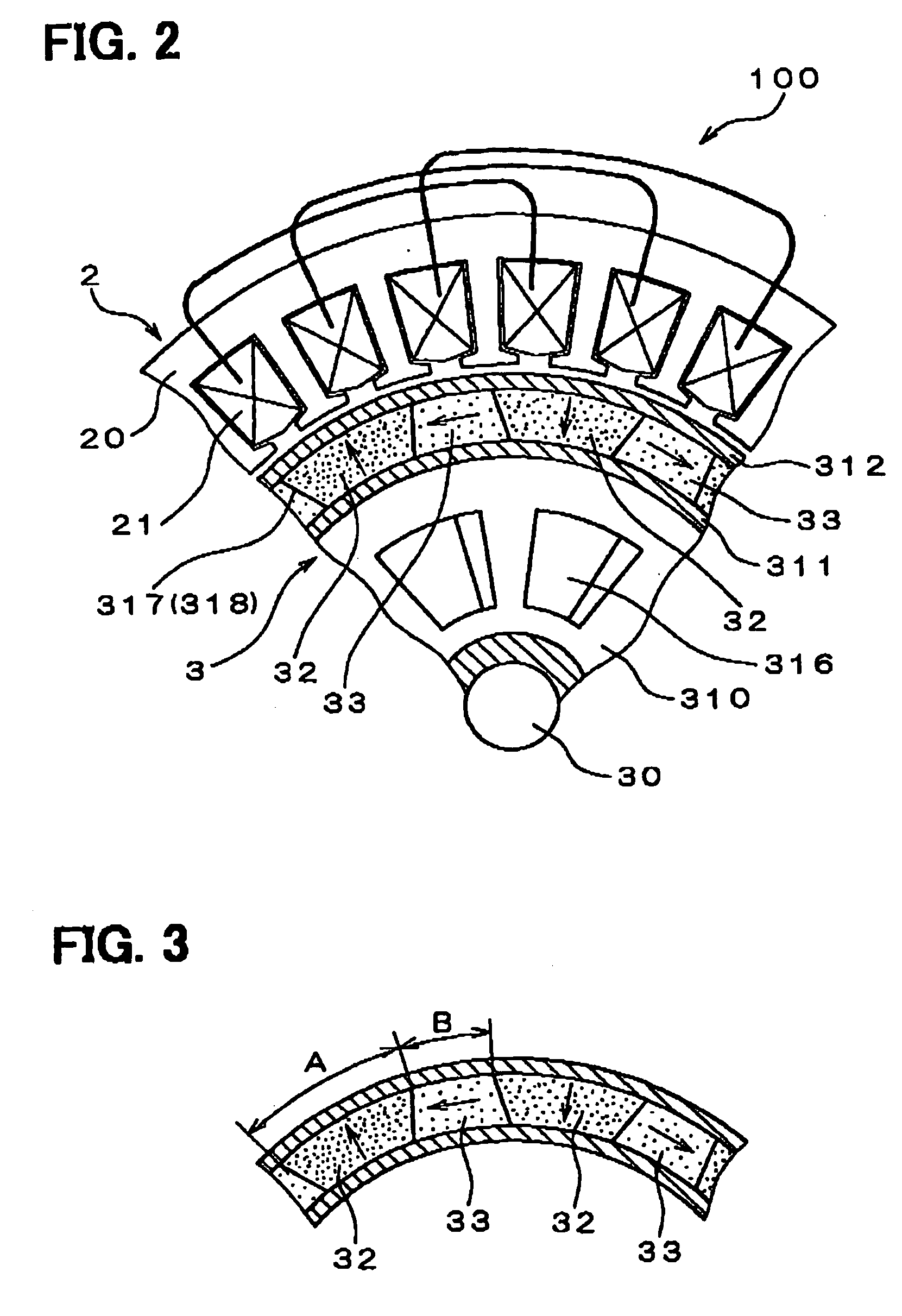
[0034] Referring to FIGS. 1 to 3, the present invention is for example employed to a vehicle ac generator 100. As shown in FIG. 1, the vehicle ac generator 100 includes a frame 1, a stator 2, and a rotor 3.

[0035] The stator 2 includes a core 20 made of a stack of core plates and a three-phase armature winding 21. The core 20 forms a plurality of teeth along its circumference, as shown in FIG. 2. The winding 21 is wound in each of slots defined between the teeth of the core 20. Furthermore, the winding 21 is wound in the slots in a pitch of 180° electrical angle so that three teeth are included in one pole pitch (180° electrical angle). The core 20 is housed and fixed to the frames 1 in a condition that an outer peripheral surface of the core 20 is cramped by an inner peripheral surface of the frame 1.

[0036] The rotor 3 is rotated to produce a rotating magnetic field linking to the stator 2. The rotor 3 is constructed of a rotation shaft 30, a hub 31, a pre...

second embodiment

[0061] (Second Embodiment)

[0062] In the second embodiment, general structure of the vehicle ac generator is similar to that of the first embodiment shown in FIG. 1. The vehicle ac generator of the second embodiment has a rotor 3A, which is different from the rotor 3 of the first embodiment. Thus, a description will be mainly made about the rotor 3A.

[0063] As shown in FIG. 5, the rotor 3A has main pole magnets 32A and yoke magnets 33A. The shape / size and materials of the main pole magnets 32A and the yoke magnets 33A are different from those of the main pole magnets 32 and the yoke magnets 33 of the first embodiment.

[0064] The main pole magnets 32A are formed of rare earth neodymium boron permanent magnets, similar to the first embodiment on the other hand, the yoke magnets 33A is formed of ferrite permanent magnets. In general, the ferrite permanent magnet has a magnetic flux density lower than that of the rare earth neodymium boron permanent magnet. Therefore, the circumferential...

third embodiment

[0065] (Third Embodiment)

[0066] In the third embodiment, general structure of a vehicle ac generator is similar to that of the first embodiment shown in FIG. 1. The vehicle ac generator of the third embodiment has a rotor 3B, which has a structure different from that of the rotor 3 of the first embodiment, as shown in FIG. 6. Thus, a description will be mainly made about the rotor 3B.

[0067] In the rotor 3B, a predetermined number of main pole magnets 32B and a predetermined number of yoke magnets 33B are arranged alternately in the circumferential direction. Each of the main pole magnets 32B are magnetized in a manner similar to the first embodiment. Also, the yoke magnets 33B are arranged such that the circumferential surfaces of each yoke magnet 33B are opposed to and abut the circumferential surfaces of the adjoining main pole magnets 32B. Here, an outside diameter of the main pole magnets 32B is smaller than the outside diameter of the yoke pole magnets 33B. Further, core pole ...


PUM


Abstract

In a rotor for a rotary electric machine, a predetermined number of main pole magnets and a predetermined number of yoke magnets are fixed in contact with a hub. Each main pole magnet is magnetized so that its radial inside portion and its radial outside portion have the opposite polarity from each other, of north pole and south pole. Also, each main pole magnet has its radial inside and radial outside polarities reversed from its closest main pole magnets. The yoke magnets are disposed to allow magnetic flux to flow through circumferential surfaces of the main pole magnets. The hub is provided as a heat radiating member and made of metal having high heat conductivity. The hub includes an inner cylindrical portion and an outer cylindrical portion, and forms an air passage spaces.

Description

CROSS REFERENCE TO RELATED APPLICATION [0001] This application is based on Japanese Patent Application No. 2003-145293 filed on May 22, 2003, the disclosure of which is incorporated herein by reference. FIELD OF THE INVENTION [0002] The present invention relates to a rotary electric machine, which is used in vehicles such as a two wheeler, a car, or a truck and in other general industrial devices, and a rotor of the same. BACKGROUND OF THE INVENTION [0003] In a Halbach array magnet rotor, a predetermined number of main pole magnets and a predetermined number of yoke magnets are alternately arranged. Each of the main pole magnets is magnetized such that its radial inside portion and its radial outside portion have the opposite polarity from each other, of north pole and south pole. Also, each main pole magnet has its radial inside and radial outside polarities reversed from its closest main pole magnets. The yoke magnets are disposed to allow magnetic flux to flow through interfaces ...

Claims


Application Information

Patent Timeline
IPC IPC(8): H02K1/20H02K1/27H02K1/32H02K9/02H02K19/22
CPCH02K1/32H02K1/278H02K1/2783
Inventor KUSASE, SHINMAEKAWA, TAKEOONISHI, TORU
Owner DENSO CORP
Why Eureka
Try Eureka