

Method and apparatus for measuring impedance across pressure joints in a power distribution system
- Summary
- Abstract
- Description
- Claims
- Application Information
AI Technical Summary
Benefits of technology
Problems solved by technology
Method used
Image

Examples
Embodiment Construction
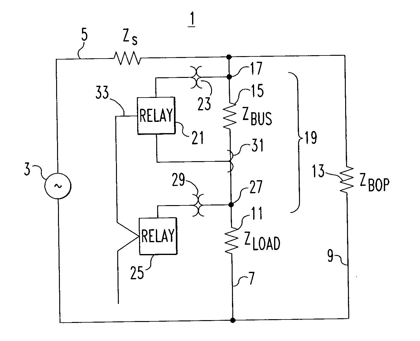
FIG. 1 is a schematic circuit diagram of an idealized ac electric power distribution system 1 to which the invention has been applied. As mentioned, the invention can also be applied to dc electric power distribution systems. The power distribution system 1 includes a power source 3 providing power through a main bus 5 to feeder buses 7 and 9. The feeder bus 7 provides the power to a load 11 while the feeder 9 provides power to other loads 13 collectively referred to as balance of plant (BOP). The power distribution system 1 upstream of the feeder buses 7 and 9 has a source impedance Zs, which is typically inductive but also has a resistive component. Impedances Zload and ZBOP of the load 11 and balance of plant 13 can be inductive, capacitive or resistive. The feeder 7 has a pressure junction 15 formed by a mechanical connection such as a bolted connection between bus bars or bus ways or cable terminal connections or the like, that has an impedance Zbus Typically, this impedance Zb...
PUM
 Abstract
Description
Claims
Application Information