Ink-jet printer, ink-jet head and method of manufacturing the ink-jet head

Active Publication Date: 2005-02-24
BROTHER KOGYO KK
View PDF11 Cites 16 Cited by
  • Summary
  • Abstract
  • Description
  • Claims
  • Application Information

AI Technical Summary

Benefits of technology

[0023] Specifically, according to another aspect of the invention, the ink-jet head may include a connection part (also called a common electrode) electrically connected to the internal electrode via through holes on the surface of the piezoelectric sheet. Then, the connection part of the piezoelectric sheet is preferably electrically connected to the internal electrode via at least two or more through holes.
[0024] According to another aspect of the invention, two or more connection systems are prepared as connection systems of the connection part and the internal electrode, even if electric connection via one through hole is disconnected, electrical connection between the connection part and the internal electrode can be kept by another through hole. That is, according to the ink-jet head of the fifth aspect, the durability and reliability of the product can be improved.
[0025] According to another aspect of the invention, the connection part is preferably provided at a position away from the electrode formation area on the surface of the piezoelectric sheet. Since the internal electrode functions as a reversed pole of the individ

Problems solved by technology

Thus, when the respective areas of the piezoelectric sheet driven by voltage application to the respective drive electrodes do not have uniform characteristics, it becomes difficult to uniformly jet ink droplets from the respective nozzles and to ob

Method used


Image

  • Ink-jet printer, ink-jet head and method of manufacturing the ink-jet head
  • Ink-jet printer, ink-jet head and method of manufacturing the ink-jet head
  • Ink-jet printer, ink-jet head and method of manufacturing the ink-jet head

Examples


Embodiment Construction

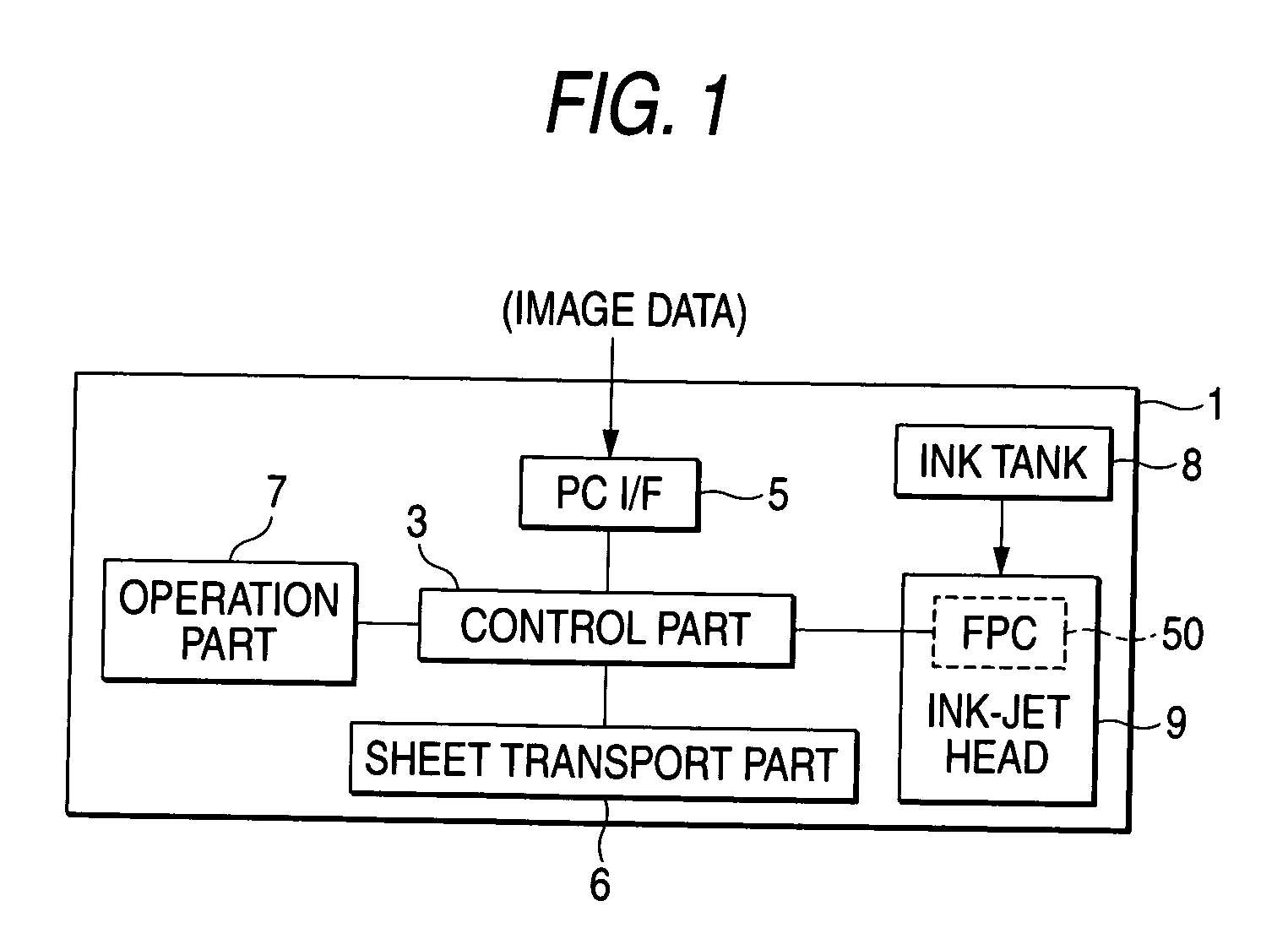
[0080] Hereinafter, an embodiment of the invention will be described with reference to the drawings. Incidentally, FIG. 1 is a block diagram showing a structure of an ink-jet printer 1 including an ink-jet head 9 to which this invention is applied.

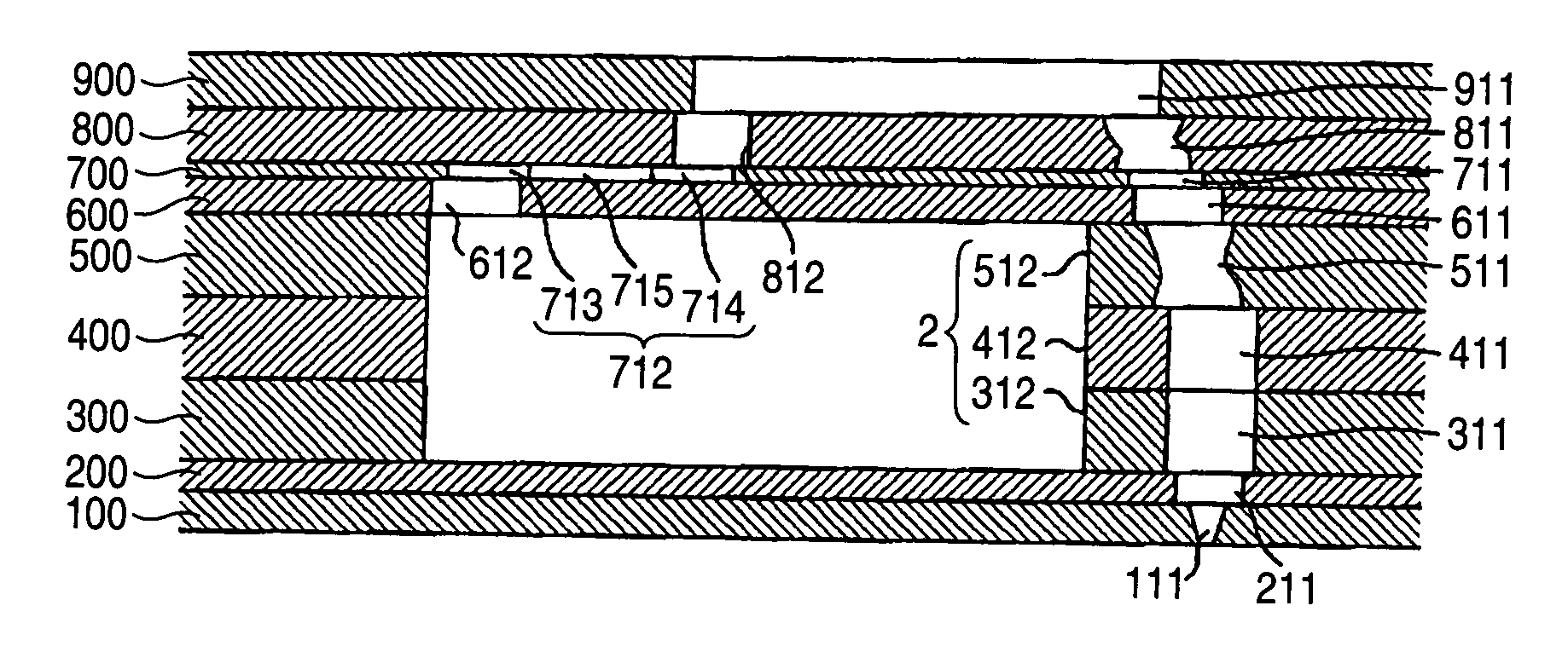
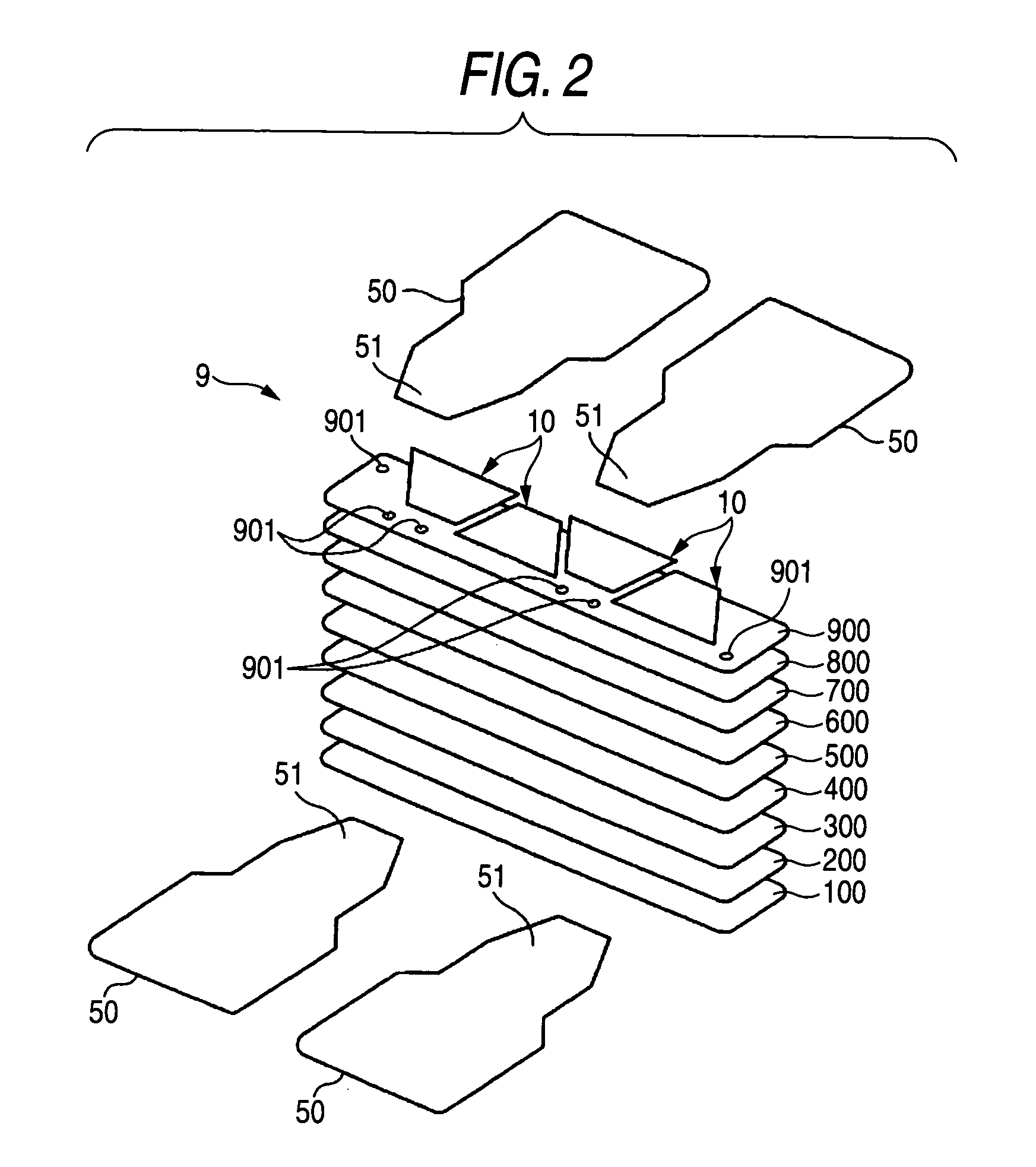
[0081] The ink-jet printer 1 of this embodiment includes a control part 3 composed of a microcomputer and the like, a PC interface 5 typified by a USB interface, a sheet transport part 6 composed of a transport roller and the like, an operation part 7 equipped with various keys necessary for a user to operate the ink-jet printer 1, an ink tank 8 filled with ink, the ink-jet head 9 which is connected to the ink tank 8, forms ink droplets of the ink provided from the ink tank 8, and jets them from nozzles 111, and the like.

[0082] A personal computer (PC) or the like is connected to the ink-jet printer 1 through the PC interface 5. When receiving picture data from the outside (PC) through the PC interface 5, the control part 3 for exercisin...


PUM

PropertyMeasurementUnit
Electric potential / voltageaaaaaaaaaa
Areaaaaaaaaaaa
Heightaaaaaaaaaa

Abstract

A piezoelectric sheet of an ink-jet head includes dummy individual electrodes in addition to individual electrodes which corresponds to respective nozzles. The dummy individual electrodes are in an outer periphery of the individual electrodes. FPC board applies drive voltage to the individual electrodes in a drive area, and deforms the area in the piezoelectric sheet in the direction of an ink pressure chamber, while the drive voltage is not applied to the individual electrodes of the non-drive area. When the dummy individual electrodes are formed in the non-drive area, a boundary area of the drive area and the non-drive area is uniformly fired when the piezoelectric sheet is manufactured. In the drive area, since surrounding structures of the respective individual electrodes become equal to one another, ink discharge characteristic is substantially uniform in the boundary area of the drive area and the non-drive area.

Description

BACKGROUND OF THE INVENTION [0001] 1. Field of the Invention [0002] The present invention relates to an ink-jet head, an ink-jet printer using the same, and a method of manufacturing the ink-jet head. [0003] 2. Description of the Related Art [0004] Conventionally, there is known an ink-jet head in which a piezoelectric element is driven, ink filled in a pressure chamber adjacent to the piezoelectric element is pressed, and the ink is jetted to a recording medium such as a paper from a nozzle communicating with the pressure chamber, so that an image is formed on the recording medium. In this kind of ink-jet head, in order to obtain an excellent picture quality, it is necessary to uniformly discharge the ink from each nozzle, and in order to raise the discharge performance of ink, various techniques have been conventionally developed. [0005] For example, in a drop-on-demand type ink-jet head as disclosed in JP-A-1-178451, in order to prevent jets of ink droplets from becoming unstable...

Claims


Application Information

Patent Timeline
IPC IPC(8): B41J2/045B41J2/055B41J2/135B41J2/14B41J2/16H05K1/00H05K1/02
CPCB41J2/14209B41J2002/14217B41J2002/14225B41J2002/14306B41J2002/14459Y10T29/42B41J2202/20H05K1/02H05K1/0393Y10T29/49147Y10T29/49401B41J2002/14491
Inventor WATANABE, HIDETOSHIHIROTA, ATSUSHI
Owner BROTHER KOGYO KK
Why Eureka
Try Eureka