Pixel structure, electro-optical apparatus, and electronic instrument

a technology of electrooptical apparatus and pixel structure, applied in the direction of identification means, instruments, light sources, etc., can solve the problems of inability to take effective steps to display line drawings, inability to take a method, and inability to accurately display lines, etc., to achieve enhanced or improved resolution at an oblique angle, simple operation, and high quality

Active Publication Date: 2005-02-24
BOE TECH GRP CO LTD
View PDF6 Cites 64 Cited by
  • Summary
  • Abstract
  • Description
  • Claims
  • Application Information

AI Technical Summary

Benefits of technology

[0042] According to this electro-optical apparatus, by a simple operation of only changing the selecting manner of the sub-pixels, either a delta arrangement or a square arrangement can be selected. Line drawing data such as characters can be displayed with the square arrangement while image data such as natural paintings can be displayed with the delta arrangement. By the delta arrangement, the resolution at an oblique angle is enhanced or improved even with low-capacitance image data, so that the natural paintings can be displayed in high quality. By the square arrangement...

Problems solved by technology

However, effective steps to display line drawings, such as characters, are not taken yet.
This method is not practical because a display with very high resolution is required for forming pseudo-hexagonal blocks with a number of square pixels.
3, FIG. 1), there is a problem of dark display because of a small area contributing to brightne...

Method used


Image

  • Pixel structure, electro-optical apparatus, and electronic instrument
  • Pixel structure, electro-optical apparatus, and electronic instrument
  • Pixel structure, electro-optical apparatus, and electronic instrument

Examples


first exemplary embodiment

[0089] (First Exemplary Embodiment of Pixel Structure)

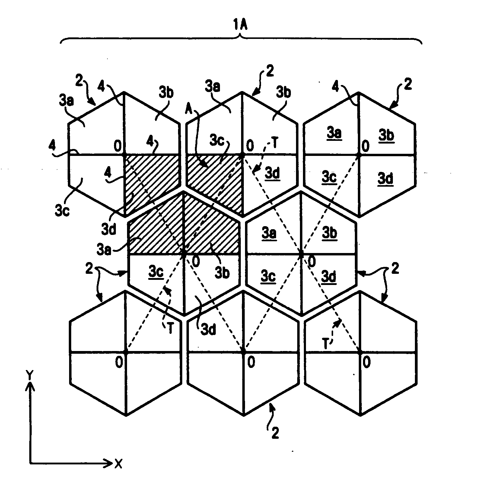
[0090] A pixel structure according to an exemplary embodiment of the present invention will be described below. The present invention is not limited to this exemplary embodiment. FIG. 1 shows part of a planar structure of the pixel structure according to the exemplary embodiment of the present invention. A pixel structure 1A shown in the drawing is a so-called honeycomb arrangement by aligning a plurality of hexagonal pixels 2 in a delta arrangement. The delta arrangement is an arrangement with the center O of each pixel 2 positioned at an apex of a triangle T indicated by broken lines.

[0091] Each of the pixels 2 is formed by arranging four sub-pixels 3a, 3b, 3c, and 3d, which are four divisions divided from the pixel 2, so that divided sides 4 of the sub-pixels are contiguous to each other. In this case, the divided sides 4 are arranged along a vertical direction Y or a horizontal direction X. The vertical direction Y agrees wi...

second exemplary embodiment

[0096] (Second Exemplary Embodiment of Pixel Structure)

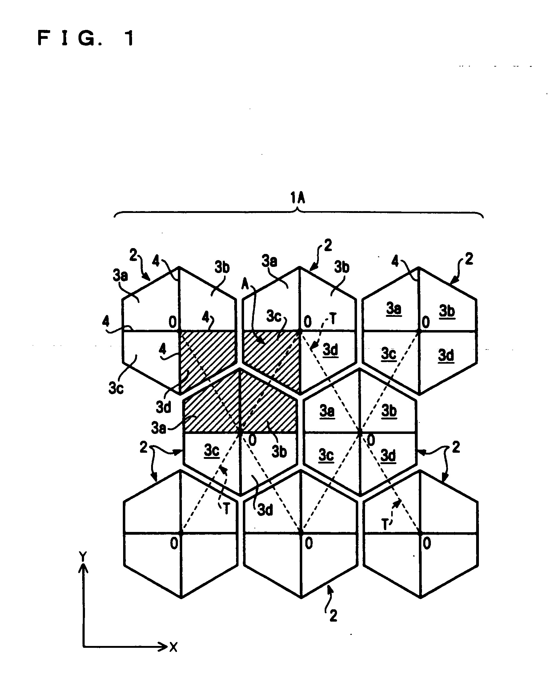
[0097]FIG. 2 shows part of a planar structure of a pixel structure according to another exemplary embodiment of the present invention. The point of a pixel structure 1B shown in the drawing different from the pixel structure 1A is that the pixel 2 shown in FIG. 2 is in a state rotated by an angle of 90° from that of the pixel 2 shown in FIG. 1. According to the exemplary embodiment, the sub-pixel 3d in one pixel 2, the sub-pixel 3c in the pixel 2 adjacent to the one pixel 2 in the vertical direction, and the sub-pixels 3a and 3b in another pixel 2 forming a delta arrangement in collaboration with these two pixels may constitute one second pixel A shown by a shaded portion. A plurality of the second pixels A are linearly aligned in both the vertical and horizontal directions Y and X.

[0098] According to the exemplary embodiment shown in FIG. 2, it is identical to the exemplary embodiment shown in FIG. 1 that a plurality of the he...

third exemplary embodiment

[0100] (Third Exemplary Embodiment of Pixel Structure)

[0101]FIG. 3 shows part of a planar structure of a pixel structure according to still another exemplary embodiment of the present invention. The point of a pixel structure 1C shown in the drawing different from the pixel structure 1A shown in FIG. 1 is that in forming sub-pixels, the pixel 2 is divided into two divisions instead of dividing into four divisions. That is, according to the exemplary embodiment, two trapezoidal sub-pixels 3a and 3b constitute the one pixel 2.

[0102] According to the exemplary embodiment, a plurality of the pixels 2 are aligned in a delta arrangement. The second pixel A, as shown by solid oblique lines of FIG. 3, is composed of the sub-pixel 3b on the right of one pixel 2 and the sub-pixel 3a on the left of the pixel 2 adjacent to the one pixel 2 in the horizontal direction X. Alternatively, the second pixel A, as shown by broken oblique lines of FIG. 3, is composed of one pixel 2 itself. Thereby, a p...


PUM


Abstract

Exemplary embodiments of the present invention include a pixel structure, an electro-optical apparatus, and an electronic instrument, which are capable of clearly displaying both images, such as natural paintings, and line drawings, such as characters, with a very simple structure. A pixel structure according to exemplary embodiments of the invention include a plurality of pixels disposed in a delta arrangement, each of the plurality of pixels having four sub-pixels that are four divisions divided from the pixel, and divided sides of the sub-pixels are arranged in a vertical direction or in a horizontal direction. In the course of display using a plurality of the pixels aligned in a delta arrangement, images, such as natural paintings, can be clearly displayed. On the other hand, in the course of display using a plurality of the second pixels A aligned in a square arrangement, line drawings, such as characters and figures, can be clearly displayed. The sub-pixel may also be shaped by dividing the pixel into two divisions.

Description

BACKGROUND OF THE INVENTION [0001] 1. Field of Invention [0002] Exemplary embodiments of the present invention relate to a pixel structure for an electro-optical apparatus, such as a liquid crystal device and an organic EL (electro-luminescence) device. Exemplary embodiments include the electro-optical apparatus using the pixel structure and an electronic instrument, such as a liquid crystal projector, a mobile phone, and a hand-held information terminal. [0003] 2. Description of Related Art [0004] A delta arrangement can display high-quality images with low-capacitance image data, and it is thereby suitable for displaying images, such as natural paintings. However, problems arise in that line drawings, such as characters and figures, become unclear. Thus, in an electro-optical apparatus mainly displaying character data, such as a computer monitor, an RGB stripe arrangement has been used in accordance with the related art. However, the stripe arrangement requires high-capacitance im...

Claims


Application Information

Patent Timeline
IPC IPC(8): G02F1/133H05B33/26G02F1/1343G09F9/30G09G3/20G09G3/30G09G3/34G09G3/36
CPCG02F1/134336G09G2300/0452G09G3/3607G02F2201/52H10K59/351H10K59/353H05B33/26
Inventor YAMAZAKI, YASUSHI
Owner BOE TECH GRP CO LTD
Why Eureka
Try Eureka