Network based multiple sensor and control device with temperature sensing and control

a multi-functional, sensor technology, applied in the field of electric sensors, can solve the problems of difficult or impossible integration of new technology developed by other manufacturers, difficult or impossible installation, future modification of component devices in the system, and usually too costly to consider, etc., to achieve the effect of convenient mounting and electrical connection, easy removal, and less tamperproo

Inactive Publication Date: 2005-02-24
ECKEL DAVID P +2
View PDF15 Cites 517 Cited by
  • Summary
  • Abstract
  • Description
  • Claims
  • Application Information

AI Technical Summary

Benefits of technology

Key elements of the present invention include (1) overcoming the difficulty of mounting diverse sensors or transducers within the same device or housing, (2) permitting these various sensors to exist in a single package that can be mounted to a wall in a substantially flush manner, (3) an embodiment that eliminates the requirement of an air flow channel in the device, thus minimizing any adverse effects on the motion detecting element or sensor as well as providing built in partial hysteresis and practical latency, and (4) an embodiment that utilizes an air flow channel in the device for drawing air over a temperature sensor and / or humidity sensor.
Another optional feature is the use of a press to release button to allow for the device to be easily removed from the wall. This allows for the device with its lighting and temperature sensor and controls to be removed from its fixed position on the wall and moved freely about the room. It can be placed in a more desirable location or can be used as a remote control as well as a regular wall mounted or table top switch or dimmer, sensor or thermostat as well as to adjust and control all natural and artificial lighting, temperature and humidity devices.

Problems solved by technology

With this type of proprietary system, the installation, servicing and future modifications of the component devices in the system were restricted to a single manufacturer's product offering and technical capability.
In addition, it was very difficult or impossible to integrate new technology developed by other manufacturers.
If technology from other manufactures could be integrated, it was usually too costly to consider.
Further, the hole in the wall is often created when the device is mounted on a wall in a home or office building.

Method used


Image

  • Network based multiple sensor and control device with temperature sensing and control
  • Network based multiple sensor and control device with temperature sensing and control
  • Network based multiple sensor and control device with temperature sensing and control

Examples


first embodiment

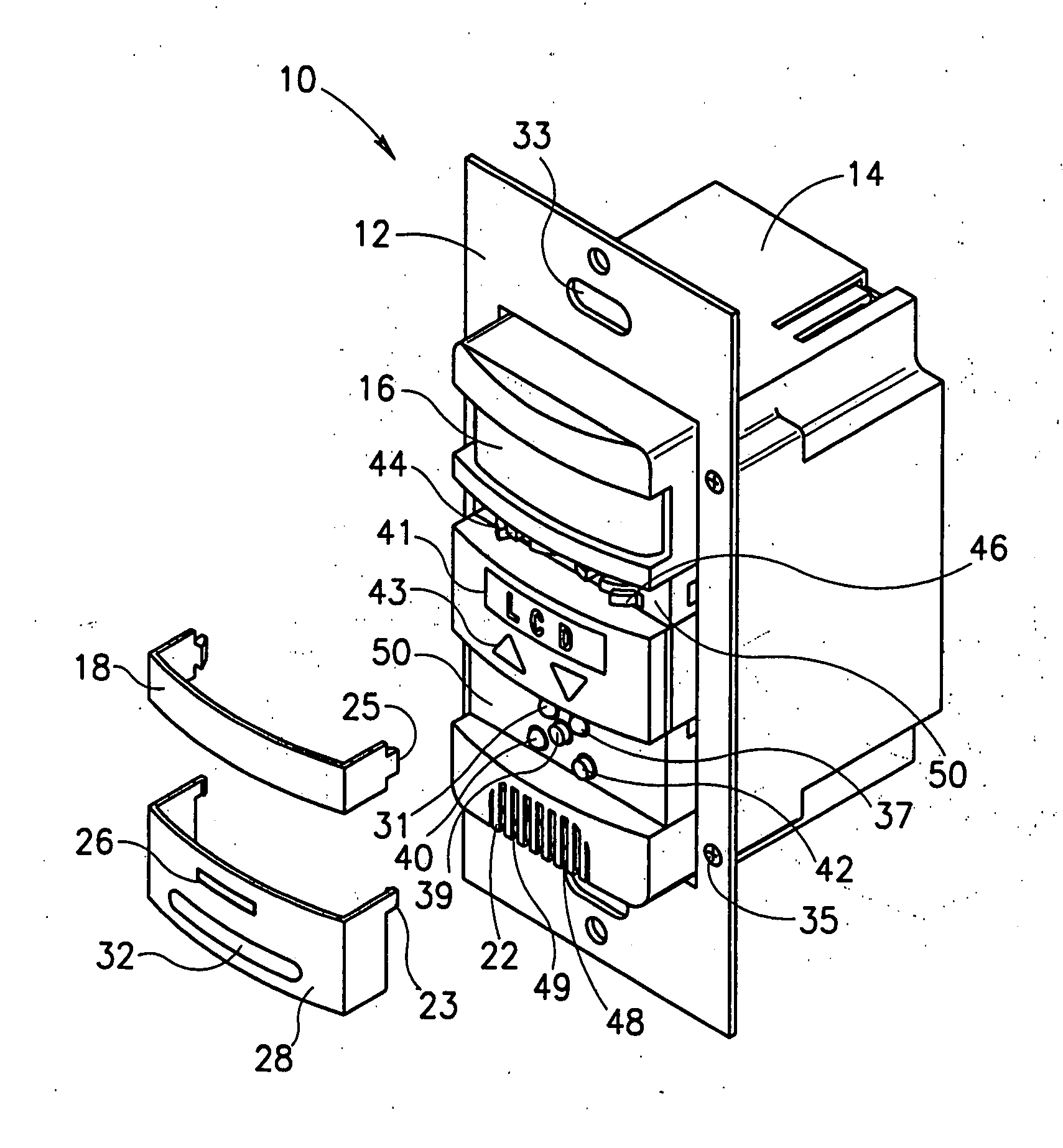
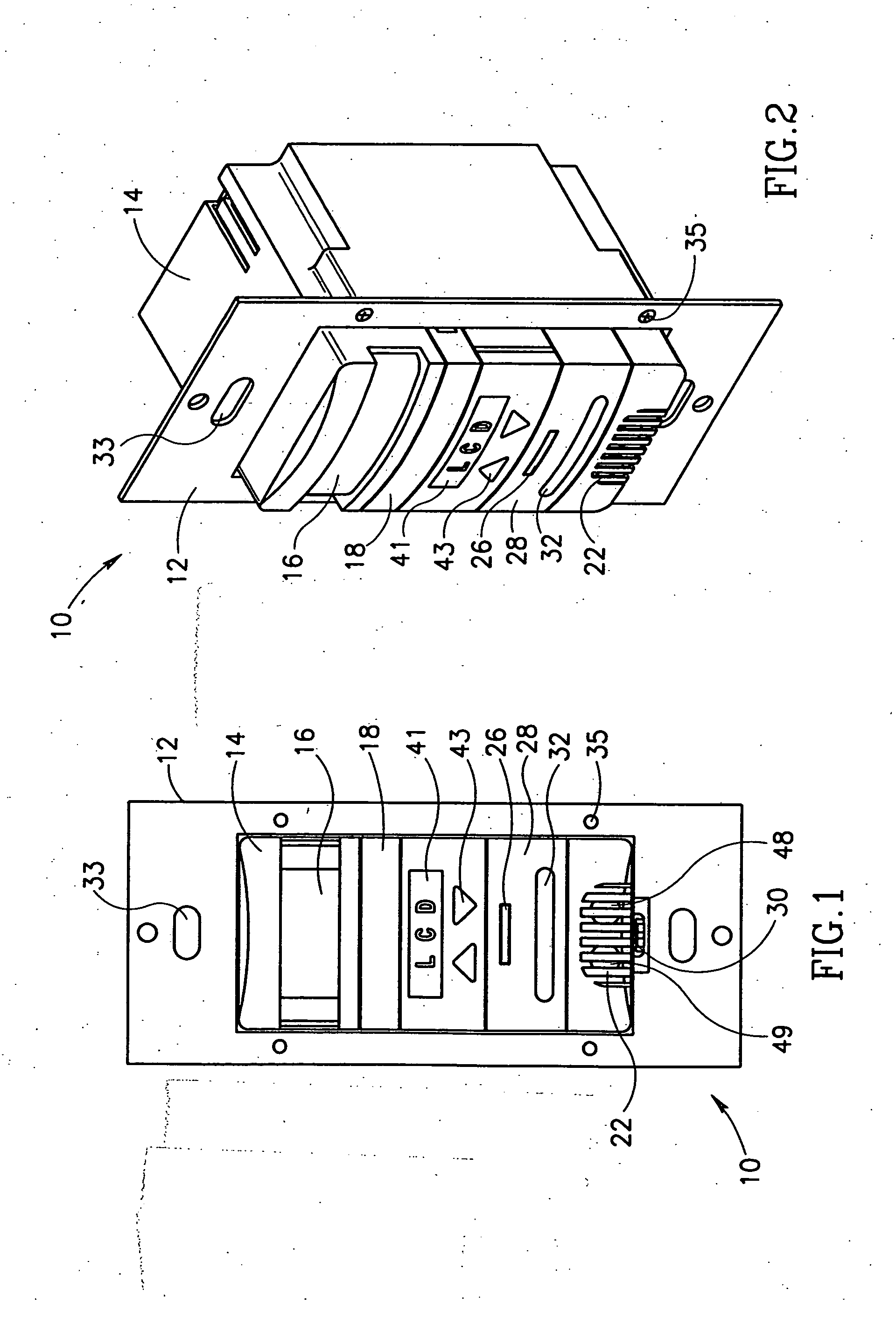
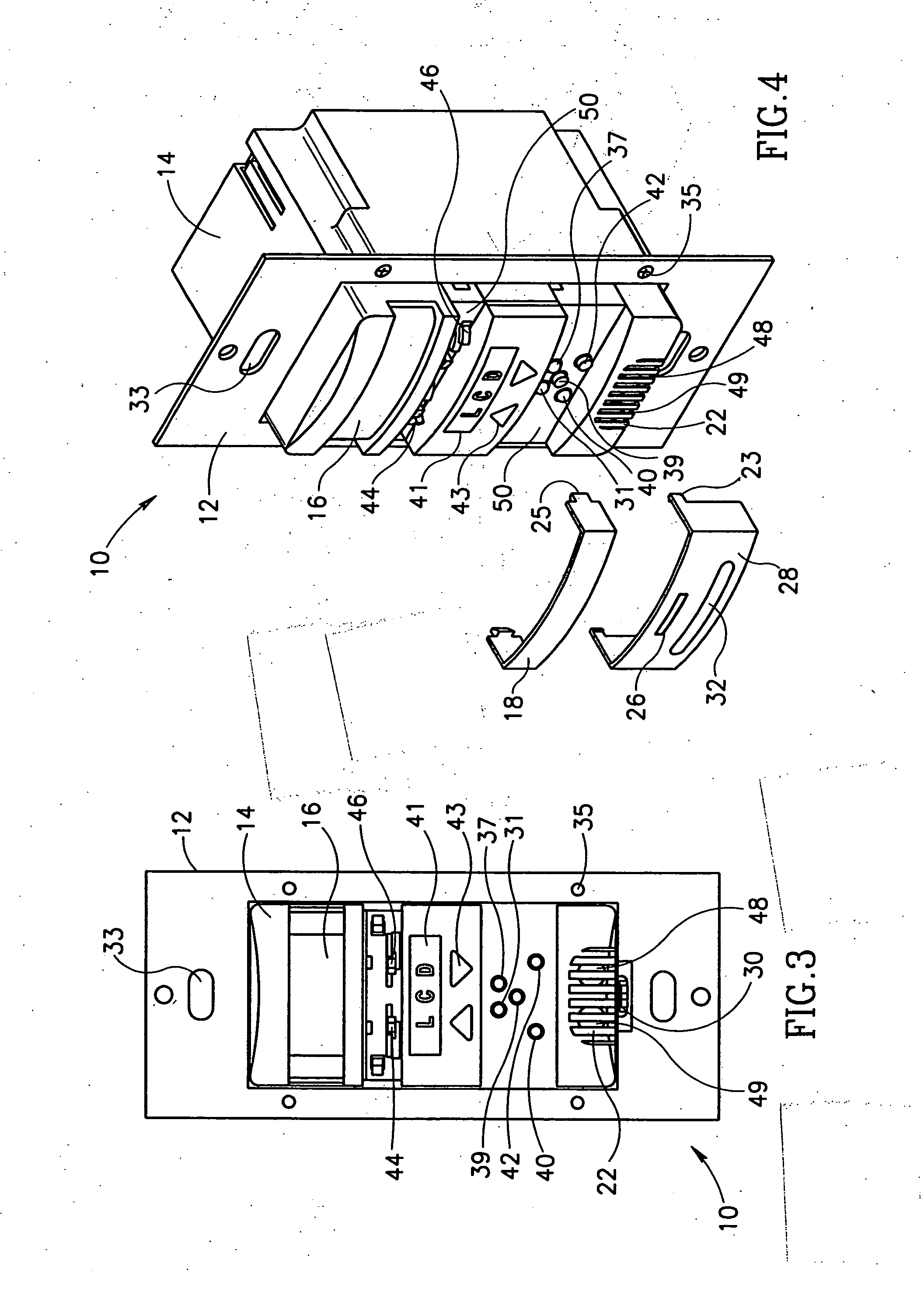
A front view illustration of the sensor / thermostat unit of the present invention incorporating PIR, temperature, humidity and ambient light sensors, thermostat control and a single switch is shown in FIG. 1. The device, generally referenced 10, comprises a housing 14 connected to a mounting plate 12 via one or more fasteners through apertures 35. The housing 14 comprises an aperture covered by a lens or window 16. The aperture is used to house an occupancy sensor, e.g., passive infrared sensor (PIR). Note that the occupancy sensor may comprise one or more PIR detectors, e.g., dual PIR detectors.

An upper cover 18, which may or may not be removable, is positioned below the motion detection element lens 16. Making the cover 18 removable permits access to adjusting levers or blinds within the device that can be used to adjust the field of view of the PIR detectors in the device.

Below the cover 18 is a display 41 for displaying information such as temperature, status, commands or othe...

second embodiment

the multi-sensor device will now be presented. The first embodiment discussed above, incorporated multiple sensors and a thermostat function with a single switch. The second embodiment presented herein incorporates two switches. A front view illustration of a second embodiment of the sensor / thermostat unit of the present invention incorporating two switches and having the upper and lower covers in place is shown in FIG. 9. The device, generally referenced 110, is similar to device 10 of FIG. 1 with the difference being that two switches are included rather than one. This embodiment is useful when it is desired to control two separate logical loads from a single device in on / off fashion.

The device comprises a mounting plate 12, housing 14, lens 16 for the PIR detectors, a removable cover 18, display 41, up and down buttons 43 and grill 22 permitting air to diffuse through to the temperature sensor 48 and humidity sensor 49. A first switch cover 122 and a second switch cover 124 are ...

third embodiment

A third embodiment also splits the switch cover 28 (FIG. 1) into two separate covers as the device of FIG. 9. A front view illustration of the sensor / thermostat unit of the present invention incorporating two switches and having the upper and lower covers in place is shown in FIG. 10. The device of FIG. 10, however, provides a dimmer function for one or more electrical loads. The switch cover 123, when pressed, functions to brighten the load as indicated by the up arrow 129 and conversely, when the switch cover 125 is pressed, the load is dimmed, as indicated by the down arrow 121.

Similar to the device of FIG. 9, the device comprises a mounting plate 12, housing 14, lens 16 for the PIR detectors, a removable cover 18, display 41, up and down buttons 43 and grill 22 permitting air to diffuse through to the temperature sensor 48 and humidity sensor 49. Also shown are the mode switch 30 which can be placed in an on, auto or off positions and the light pipe 126 which provides a light p...


PUM

PropertyMeasurementUnit
period of timeaaaaaaaaaa
voltageaaaaaaaaaa
voltageaaaaaaaaaa

Abstract

A multifunction sensor device which provides various transducer functions including means for performing temperature sensing, humidity sensing, ambient light sensing, motion detection, thermostat functions, switching functions, load switching and dimming functions, displaying actual and set temperature values, displaying time of day values and a means to put the device in an on, off or auto mode. The device has utility in environments such as that found in offices, schools, homes, industrial plants or any other type of automated facility in which sensors are utilized for energy monitoring and control, end user convenience or artificial or natural cooling, heating and HVAC control. The device can be used as a switch or dimmer, sensor or thermostat as well as to adjust and control all natural and artificial lighting, temperature and humidity devices. Key elements of the invention include overcoming the difficulty of mounting diverse sensors or transducers within the same device or housing; permitting these various sensors to exist in a single package that can be mounted to a wall in a substantially flush manner; and eliminating the requirement of an air flow channel in the device, thus minimizing any adverse effects on the motion detecting element or sensor as well as providing built in partial hysteresis. The device may include additional transducers or sensors and is constructed such that the temperature and humidity sensors are neither exposed to the flow of air in a room or area nor in an airflow channel whereby a chimney effect may occur. The device can transmit and receive real time data, relative data and actual discrete data in addition to switching and controlling loads locally or remotely. An embodiment utilizing airflow channels to direct air over the temperature and humidity sensors is also disclosed.

Description

FIELD OF THE INVENTION The present invention relates generally to the field of electrical sensors and more particularly to a network based multi-function sensor and control device suitable for sensing motion, temperature, humidity and ambient light, setting and controlling temperature and control relay and ballast loads and which includes blinder devices for reducing nuisance tripping of the device. BACKGROUND OF THE INVENTION Today, automation systems are being installed in more and more buildings, including both new construction and in structures that are being rebuilt. The incentives for putting automation systems into a building are numerous. High on the list are reduced operating costs, more efficient use of energy, simplified control of building systems, ease of maintenance and of effecting changes to the systems. Facility managers would prefer to install systems that can interoperate amongst each other. Interoperability is defined by different products, devices and systems ...

Claims


Application Information

Patent Timeline
Patent Type & Authority Applications(United States)
IPC IPC(8): G01K1/04G01K1/08H05B37/02H05B41/392
CPCG01K1/045G01K1/08H05B37/02H05B37/0218Y02B20/46H05B37/0245H05B37/0254H05B41/3922Y02B20/44H05B37/0227H05B47/18H05B47/175H05B47/11H05B47/10H05B47/105Y02B20/40H05B47/17H05B47/13
Inventor ECKEL, DAVID P.BONASIA, GAETANOPORTER, JAMES A.
Owner ECKEL DAVID P
Why Eureka
Try Eureka