Remote interface optical network

a remote interface and optical network technology, applied in the field of computer network systems, can solve problems such as server management problems, unnecessary heat disbursement issues, and occupying valuable rack spa

Inactive Publication Date: 2005-02-24
GLOBAL EAGLE ENTERTAINMENT
View PDF114 Cites 86 Cited by
  • Summary
  • Abstract
  • Description
  • Claims
  • Application Information

AI Technical Summary

Benefits of technology

[0017] These and other problems are solved by a remote interface network in which multiple remote HID encoder/decoder units share a common physical transport medium for connecting to one or more processing unit encoder/decoders. In one embodiment, the physical transport medium includes an optical shared media transport network. Each remote HID encoder/decoder unit can support one or more remote HIDs. The processing unit encoder/decoder can support one or more Pus. The network can be used, for example, in office, hospital, dense seat (e.g., aircraft, bus, etc.) and content provider networks.
[0018] In one embodiment, a remote interface network provides multiple remote human interface device encoder/decoder units that can share a common physical transport medium for connecting to one or more processing unit encoder/decoders. Each remote encoder/decoder unit can support one or more remote devices some of which can be human interface devices. The processing unit encoder/decoder can support one or more processor units.
[0019] In one embodiment, an HID network provides one or more remote stations having a set of interface devices associated with a user and a station encoder/decoder. A digital transport network is provided to connect to one or more content sources (PUs) through a crossbar switch. The encoders convert native format signals into one or more serial bit streams for transport over the digital transport network. The decoders convert one or more serial bitstreams into native format signals to drive native devices. The crossbar can be configured to broadcast one processing unit channel to multiple stations, to multi-cast one processing unit channel to multiple stations, to form a point to point connection between one processing unit and one station, or a combination of multicast and point to point connections. The control of the crossbar can be external, from control signals extracted from the station's serial bit streams as they enter the cross bar, or from control signals from the processor units.
[0020] In one embodiment, a remote device interface network, includes a first processing unit configured to provide at least a first raw video output signal for a first video display, a second processing unit configured to provide at least a second raw video output signal for a second video display, a first processor-side encoder/decoder configured to convert the first raw video output signal into a first serial digital sampled data stream, a second processor-side encoder/decoder configured to convert the second raw video output signal into a second serial digital sampled data stream, a first HID-side encoder/decoder configured to convert the first serial digital sampled data stream into a representation of the first raw video output signal, a second HID-side encoder/decoder configured to convert the second serial digital sampled data stream into a representation of the second raw video output signal and to convert signals from an output signal from a human interface device into a third serial digital sampled data stream, and a shared-media transport layer configured to provide bi-directional communication between the first and second processor-side encoder/decoders and the first and second HID-side encoder/decoders by transporting the first and second serial digital sampled data streams in a downstream direction and transporting the third serial digital sampled data stream in an upstream direction. In one embodiment, the shared-media transport layer includes a fiberoptic system. In one embodiment, the shared-media transport layer includes single-mode fiber. In one embodiment, the transport layer includes coaxial cable. In one embodiment, the transport layer includes twisted-pair cable. In one embodiment, the first raw video output signal includes a VGA video signal. In one embodiment, the first raw video output signal includes an NTSC video signal. In one embodiment, the first raw video output signal includes a PAL video signal. In one embodiment, the first raw video output signal includes a digital television signal. In one embodiment, the first raw video output signal includes a composite video signal. In one embodiment, the first raw video output signal includes an S-video signal. In one embodiment, the first raw video output signal includes a RGBY video signal. In one embodiment, the first raw video output signal includes an uncompressed video signal. In one embodiment, the first raw video output signal includes a Digital Video Interface (DVI) video signal. In one embodiment, the first raw video output signal includes a DVI-analog video signal. In one embodiment, The remote device interface network of claim 1, wherein the first raw video output signal includes a DVI-digital video signal. In one embodiment, the first raw video output signal includes a Low Voltage Differential Interface (LVDS) video signal. In one embodiment, the output signal from a human interface device includes a USB signal. In one embodiment, the output signal from a human interface device includes an Ethernet-compatible waveform. In one embodiment, the output signal from a human inte

Problems solved by technology

In the early 1980's, as the computer industry grew, many server rooms and data centers were faced with the problem of having dozens and even hundreds of monitors, keyboards, and mice, taking up valuable rack space, and adding unnecessary heat disbursement issues.
They also created server management problems for larger data centers in which technicians had to physically walk to each server they needed to work on.
However, handling large amount of servers with these KVM switches is cumbersome at best, and impractical if more than one user requires simultaneous access.
These include security, as a rogue employee can gain access to critical information on a distributed computer's hard drive; the introduction of illegal, inappropriate or dangerous software onto the computing system; damage due to an unauthorized employee attemptin

Method used


Image

  • Remote interface optical network
  • Remote interface optical network
  • Remote interface optical network

Examples


Embodiment Construction

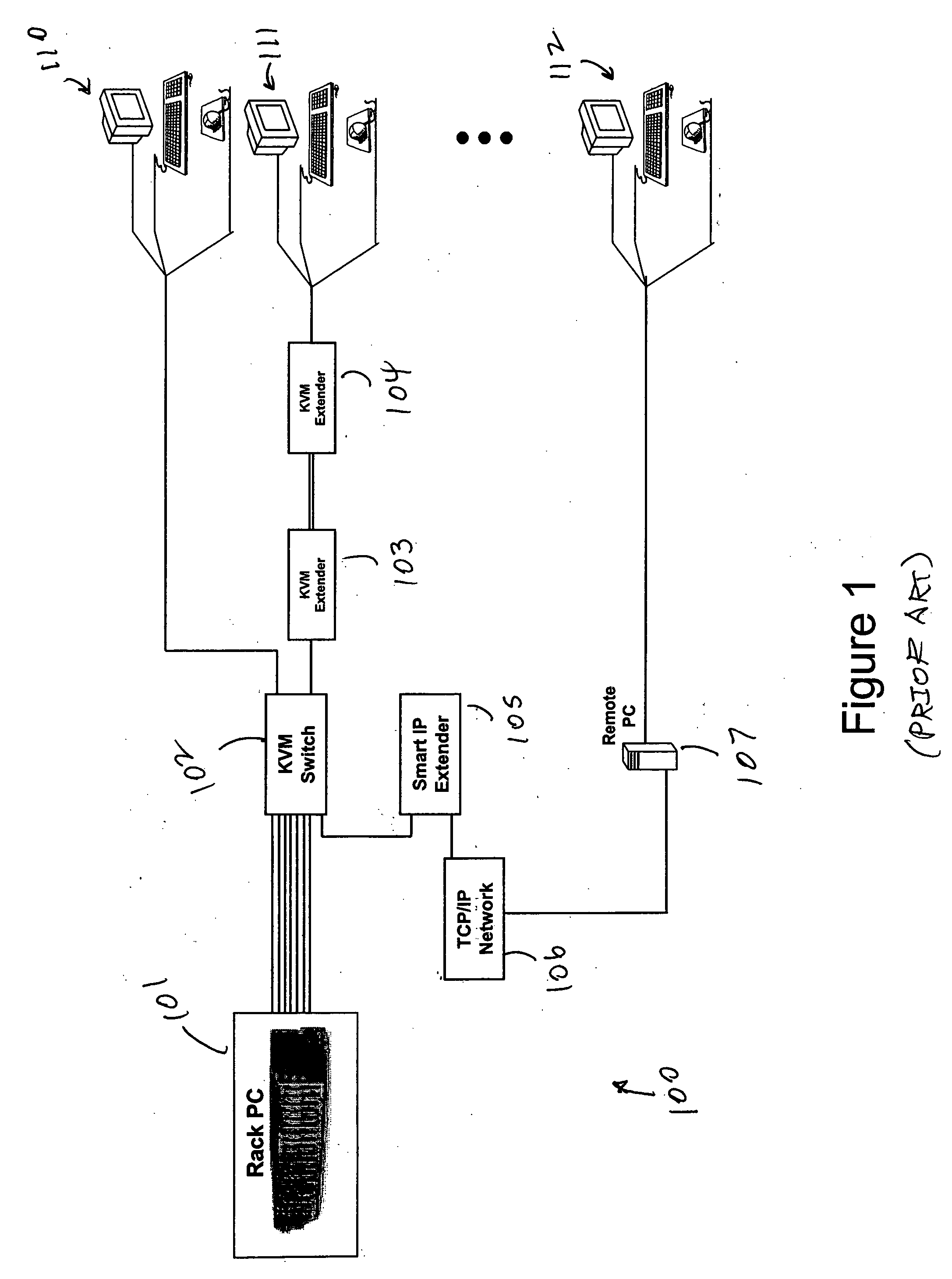
[0031]FIG. 1 shows an example of a KVM remote interface network 100. In the network 100, keyboard, video, and mouse interfaces on a racked PC 101 (or PCs) are provided via a “KVM cable” to a processor-side KVM interface on a KVM switch 102. To reduce the wiring complexity, most KVM component suppliers offer combined keyboard-video-mouse cables, called “KVM cables”, which break out the component cables at both ends. Multiple keyboard-monitor-mouse sets are typically attached to the device side of the KVM switch 102. In this example, a keyboard-monitor-mouse set 110 is provided to the KVM switch, a keyboard-monitor-mouse set 111 is provided to the KVM switch 102 through a KVM extender 103,104, and a keyboard-monitor-mouse set 111 is provided to the KVM switch 102 by TCP / IP by using a PC 107, TCP / IP network 106, and IP Extender 105. Typically, a defined key sequence on one or more of the keyboards in the keyboard-monitor-mouse set 110-111 allows a user to control the KVM switch 102.

[0...


PUM


Abstract

A remote interface network in which multiple remote HID encoder/decoder units share a common physical transport medium for connecting to one or more processing unit encoder/decoders is described. In one embodiment, the physical transport medium includes an optical shared media transport network. Each remote HID encoder/decoder unit can support one or more remote HIDs. The processing unit encoder/decoder can support one or more Pus. The network can be used, for example, in office, hospital, dense seat (e.g., aircraft, bus, etc.) and content provider networks.

Description

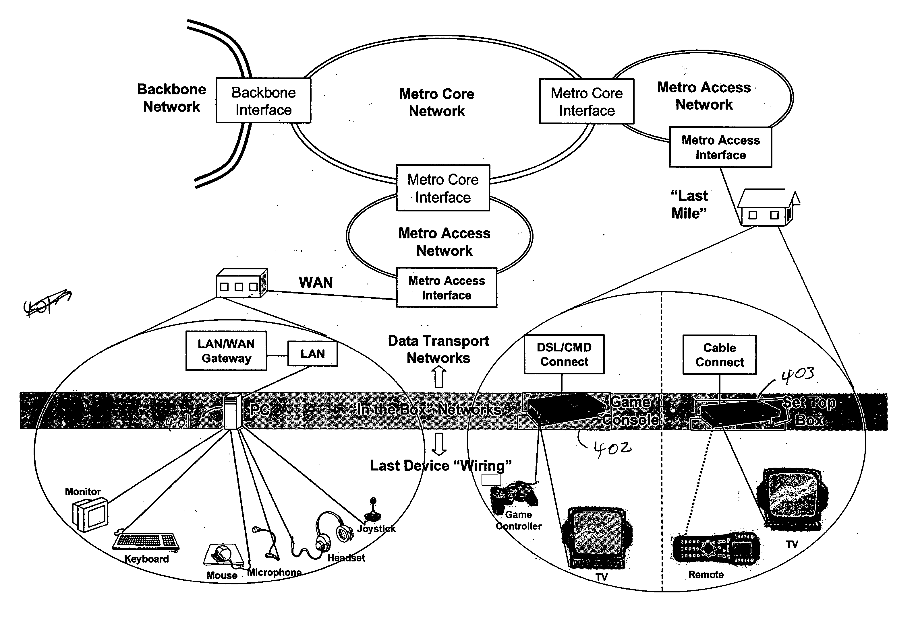
REFERENCE TO RELATED APPLICATION [0001] The present application claims priority benefit of U.S. Provisional Application No. 60 / 478,732, filed Jun. 13, 2003, “REMOTE INTERFACE OPTICAL NETWORKS,” the entire contents of which is hereby incorporated by reference.BACKGROUND [0002] 1. Field of the Invention [0003] The present disclosure relates to computer network systems. [0004] 2. Description of the Related Art [0005] Optical transport networks are in use or have been proposed for a number of network classes. These include backbone networks, metro core networks, metro access networks, and local access or “last mile” networks. The move to optical transport networks has been in response to the demand for increased network capacity. The key drivers that have led to this demand include the continued growth of Internet traffic, the emergence of residential broadband services market, and the emerging mobile Internet market. Several “all optical” networks have been proposed to service various ...

Claims


Application Information

Patent Timeline
IPC IPC(8): A63F13/12G06F15/16H04N7/15H04N7/24
CPCA63F13/12A63F2300/409G06F3/0227G06F3/023H04N21/4622H04N7/152H04N21/214H04N21/2381H04N21/4363G06F3/1454A63F13/30H04N7/14A63F13/338
Inventor PETRISOR, GREGORY C.
Owner GLOBAL EAGLE ENTERTAINMENT
Why Eureka
Try Eureka