
Method, medium, and system visually compressing image data

a technology of image data and compression method, applied in the field of image encoder/decoder system, can solve problems such as picture quality problem, subjective picture quality performance deterioration, and shifting pixel values among neighboring pixels, so as to improve subjective picture quality and reduce the complexity of the image encoder/decoder system

Active Publication Date: 2008-06-05
SAMSUNG ELECTRONICS CO LTD
View PDF11 Cites 61 Cited by
  • Summary
  • Abstract
  • Description
  • Claims
  • Application Information

AI Technical Summary

Benefits of technology

[0014]One or more embodiments of the present invention provides a system, medium, and method enhancing subjective picture quality, thereby significantly lowering the complexity of an image encoder / decoder system, and providing a picture-based Control Bit Rate (CBR) suitable for a Liquid Crystal Display Dynamic Capacitance Compensation (LCD DCC) device, when images are reconstructed.

Problems solved by technology

However, these standards exhibit the following problems when they are applied to LCD DCC devices.
First, there is a picture quality problem that occurs.
However, in the case of the JPEG or H.264 standard based on transform coding, subjective picture quality performance deteriorates.
Another problem related to transform coding compression occurs when images shift in units of a pixel, e.g., with an object within the image moving, thereby shifting pixel values among neighboring pixels.
Second, since all of the above-mentioned image compression techniques are based on entropy coding, a critical path is created when images are decoded, and accordingly the complexity of a decoder significantly increases.
In particular, in the case of the JPEG and H.264 standards that perform transform coding in a unit of a block, the complexity of a decoder further increases.
Furthermore, since the H.264 standard uses intra prediction, the amount of memory use increases and the complexity of a decoder further increases.
Third, all of the above-mentioned image compression techniques allow bit rate control to some degree, however, they cannot generate an exact bit rate.
For example, when the above-mentioned image compression techniques control a bit rate to achieve ⅓ compression, the bit rate will be limited within ⅓ compression due to the capacity limitation of a memory used in the corresponding LCD DCC device.
However, if bit rate control fails, the data cannot be compressed to less than ⅓ of the original amount.

Method used


Image

  • Method, medium, and system visually compressing image data
  • Method, medium, and system visually compressing image data
  • Method, medium, and system visually compressing image data

Examples


Embodiment Construction

[0048]Reference will now be made in detail to embodiments, examples of which are illustrated in the accompanying drawings, wherein like reference numerals refer to the like elements throughout. Embodiments are described below to explain the present invention by referring to the figures.

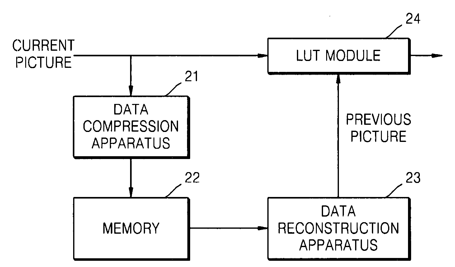
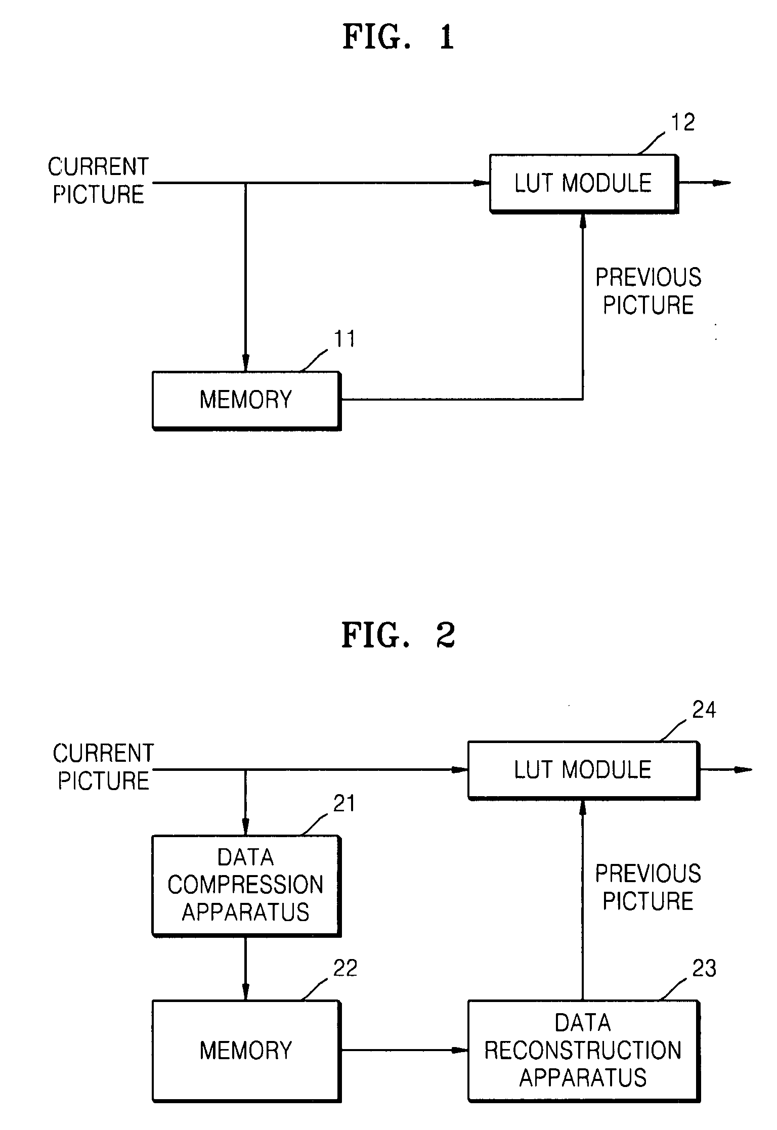
[0049]FIG. 2 illustrates a portion of a LCD DCC device / system, according to an embodiment of the present invention.

[0050]Referring to FIG. 2, the LCD DCC device may include a data compression system 21, a memory 22, a data reconstruction system 23, and a LUT module 24, for example.

[0051]The data compression system 21 may compress data, e.g., using one of two data compression methods, that is, a Differential Pulse Code Modulation (DPCM) method and a Pulse Code Modulation (PCM) method, for example.

[0052]The memory 22 may receive and store the compressed data from the data compression system 21. By performing this operation, when a current picture is received, the previous picture may already be stored i...


PUM


Abstract

A method, medium, and system compressing and / or reconstructing image data. The data compression method includes compressing current data according to a plurality of modes for compressing current data, determining whether the current data compressed according to the plurality of modes can be represented by a fixed length of bits, selecting a mode from among modes in which the compressed current data can be represented by the fixed length of bits, and outputting the compressed current data according to the selected mode. Accordingly, it is possible to significantly lower the complexity of an image encoder / decoder system, and exactly meet a picture-based Control Bit Rate (CBR) suitable for a Liquid Crystal Display Dynamic Capacitance Compensation (LCD DCC) device / system.

Description

CROSS-REFERENCE TO RELATED APPLICATIONS[0001]This application claims the priority of Korean Patent Application No. 2006-0120191, filed on Nov. 30, 2006, in the Korean Intellectual Property Office, the disclosure of which is incorporated herein in its entirety by reference.BACKGROUND[0002]1. Field of the Invention[0003]One or more embodiments of the present invention relate to a system of compressing and / or reconstructing image data, and more particularly, to an image encoder / decoder system suitable for Liquid Crystal Display Dynamic Capacitance Compensation (LCD DCC) devices.[0004]2. Description of the Related Art[0005]FIG. 1 illustrates a portion of a conventional Liquid Crystal Display Dynamic Capacitance Compensation (LCD DCC) device.[0006]Referring to FIG. 1, the conventional LCD DCC device includes a memory 11 and a Lookup Table (LUT) module 12. The LCD DCC device is used to apply a voltage higher than a required voltage to the pixels of a Thin Film Transistor (TFT)-LCD panel, ...

Claims


Application Information

Patent Timeline
IPC IPC(8): H04N7/26H03M7/30H04N1/413H04N19/103H04N19/11H04N19/12H04N19/134H04N19/136H04N19/154H04N19/176H04N19/186H04N19/196H04N19/42H04N19/423H04N19/46H04N19/50H04N19/593H04N19/70H04N19/85H04N19/91
CPCH04N19/63H04N19/115H04N19/61H04N19/90H04N19/146H04N19/436H04N19/593H04N19/103
Inventor LEE, SANG-JOLEE, SI-HWAKIM, DO-HYUNG
Owner SAMSUNG ELECTRONICS CO LTD
Learn More