Multi-link piston crank mechanism for internal combustion engine
- Summary
- Abstract
- Description
- Claims
- Application Information
AI Technical Summary
Benefits of technology
Problems solved by technology
Method used
Image
Examples
first embodiment
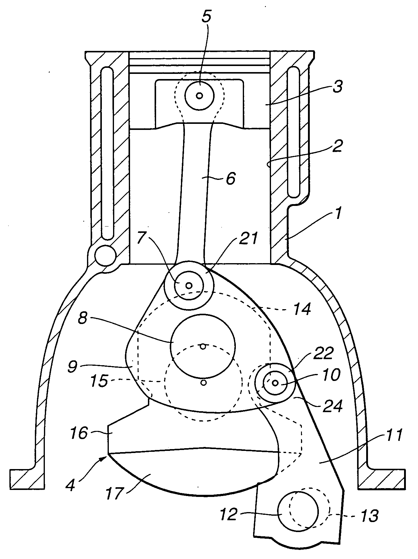
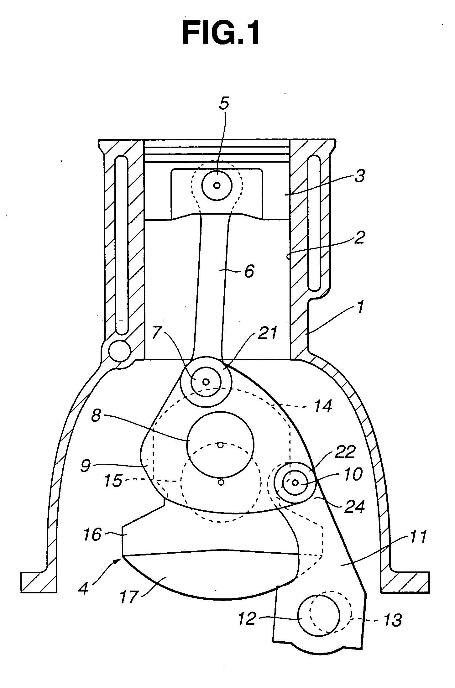
[0022] Referring to FIGS. 1-3, a multi-link piston crank mechanism of the present invention is explained. As illustrated in FIG. 1, an internal combustion engine includes cylinder block 1. Cylinder block 1 has a plurality of engine cylinders 2, only one of which is shown in FIG. 1. Piston 3 is slidably disposed in engine cylinder 2. Crankshaft 4 is rotatably supported by cylinder block 1.
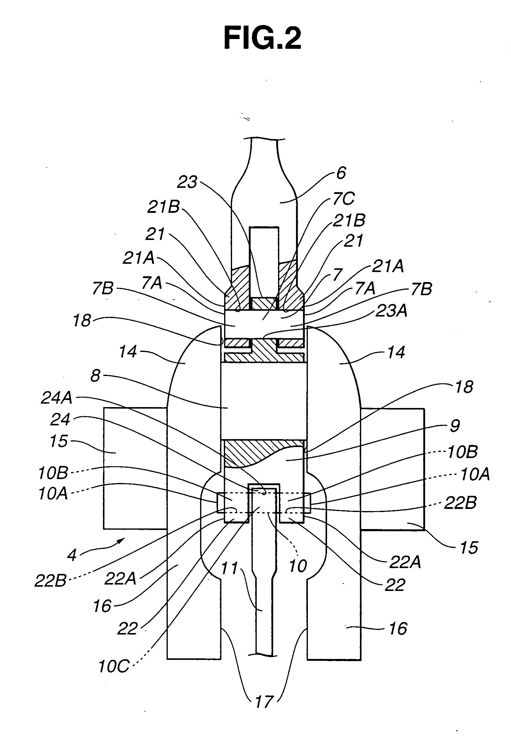
[0023] Upper link 6 extends downward from piston 3. Upper link 6 has an upper end portion connected to piston 3 through piston pin 5. Upper link 6 has a lower end portion pivotally connected to an outer peripheral portion of lower link 9 through connection pin 7 hereinafter referred to as upper pin 7. Lower link 9 has a central portion pivotally disposed on crank pin 8 of crankshaft 4, and an outer peripheral portion connected to an upper end portion of control link 11 through connection pin 10 hereinafter referred to as control pin 10. Lower link 9 thus has two connecting portions at the outer peri...
second embodiment
[0036] Referring to FIGS. 7A-7D, an operation of assembling the multi-link piston crank mechanism of the second embodiment will be explained hereinafter. First, as illustrated in FIG. 7A, piston 3, piston pin 5, upper link 6, upper pin 7 and one link part 9A of lower link 9 are coupled together. At this time, upper link 6 and one link part 9A are coupled to each other by merely inserting upper pin 7 into pin insertion holes 21B, 21B of upper link 6 and pin insertion hole 23A of one link part 9A. Subsequently, as shown in FIG. 7B, one link part 9A is placed on crank pin 8 while keeping the coupling state of piston 3, piston pin 5, upper link 6, upper pin 7 and one link part 9A. In this state, upper pin 7 is interposed between the pair of thrust surfaces 18, 18 of crank webs 14, 14. Axial displacement of upper pin 7 is thus limited by the mutual contact between end surfaces 7A, 7A and thrust surfaces 18, 18. Upper pin 7 is prevented from falling out of the space between thrust surface...
PUM
 Abstract
Description
Claims
Application Information
 - R&D
- Intellectual Property
- Life Sciences
- Materials
- Tech Scout
- Unparalleled Data Quality
- Higher Quality Content
- 60% Fewer Hallucinations
Browse by: Latest US Patents, China's latest patents, Technical Efficacy Thesaurus, Application Domain, Technology Topic, Popular Technical Reports.
© 2025 PatSnap. All rights reserved.Legal|Privacy policy|Modern Slavery Act Transparency Statement|Sitemap|About US| Contact US: help@patsnap.com


