
Method and apparatus for reduction of fluid-borne noise in hydraulic systems

a technology of hydraulic system and fluid-borne noise, which is applied in the direction of liquid/fluent solid measurement, volume/mass flow by differential pressure, instruments, etc., can solve the problems of objectionable acoustic noise, hydraulic system fluid-borne noise is commonly present, mechanical apparatus, hydraulic lines, etc., to reduce or eliminate noise, minimize or eliminate turbulence

Inactive Publication Date: 2005-03-03
COUPLED PRODS
View PDF26 Cites 25 Cited by
  • Summary
  • Abstract
  • Description
  • Claims
  • Application Information

AI Technical Summary

Benefits of technology

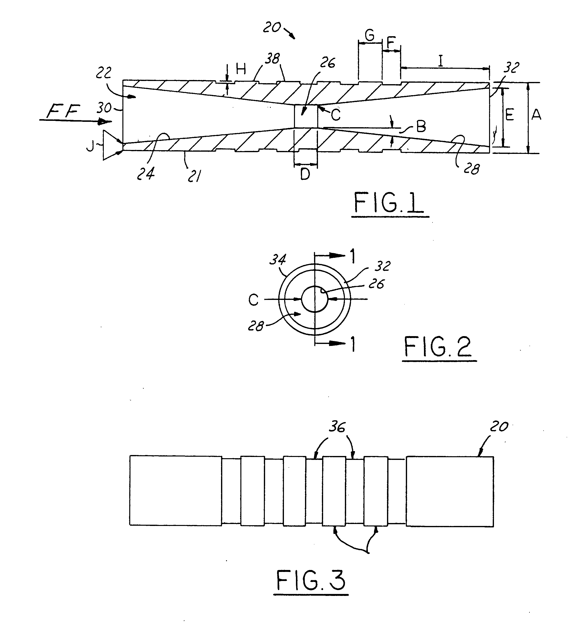
[0008] Accordingly, and by way of summary description, and not by way of limitation, the present invention is directed to providing a new form of restrictor for use in noise-reduction fluid conduits subject to pressure pulsations. The restrictor has a central flow-through passage open at its opposite axial ends, but this flow-through passage is configured in the form of a classic venturi instead of the conventional constant diameter flow-through passage. In a present preferred but exemplary embodiment of the invention, the restrictor has its flow-through passage configured as a venturi having a shallow convergent (in the direction of fluid flow) tapered inlet, a constant diameter throat and a shallow divergent (in direction of fluid flow) tapered outlet. The restrictor flow-through passage is thus constructed with the configuration of a venturi inlet, throat and outlet arranged and operable, under the pressure and fluid flow conditions in which the restrictor is used, so as to minimize turbulence in the restrictor outlet and / or immediately downstream thereof.
[0009] Preferably the cross sectional configuration of the interior of the restrictor is symmetrical about all axes, and the taper angle for both the inlet and the outlet is approximately 8°. Although the restrictor can be made of metallic material such as brass, aluminum or steel, it is preferred to injection mold the restrictor out of a suitable plastic material to achieve smoother wall surfaces in the flow-through passage, as well as for economy of system assembly and part costs.
[0010] In accordance with the method of the invention, the venturi inlet, throat and outlet are designed so as to conduct fluid therethrough in the operating system of the pressure fluid device by matching the characteristics of the fluid, the operational pressures, fluid density and other relevant system parameters, such that the venturi operates below the lower critical value of the Reynolds number of the fluid flow through the restrictor to thereby minimize or eliminate noise by minimizing or eliminating turbulence in the fluid in the restrictor outlet and / or exiting immediately downstream from the venturi restrictor. As indicated hereinabove, the venturi restrictor of the invention is presently intended primarily for use in the power steering return line to the system reservoir that supplies the pump input side of the power steering circuit where fluid pressures of 100 to 150 psi are typical, because this appears to be the area where the turbulence problems are most acute and are manifesting themselves with the annoying “hiss” noise. However, the preferred embodiment of the restrictor, due to its other advantageous features as well as the venturi shape of the flow-through passage, may also be advantageously employed in the high pressure side of the power steering circuit as a central restrictor in the typical tuning cable assembly employed in this side of the system.

Problems solved by technology

Fluid-borne noise is commonly present in hydraulic systems powered by pumping apparatus such as gear, vane or piston pumps.
Typically, the noise results when pressure waves generated as pump flow ripple encounter system flow impedance.
Fluid-borne noise present in a hydraulic system causes mechanical apparatus, such as hydraulic lines, control valves, hydraulic motors, and supporting structural members, to vibrate.
In many cases, such vibration is coupled to the atmosphere and is the source of objectionable acoustic noise.
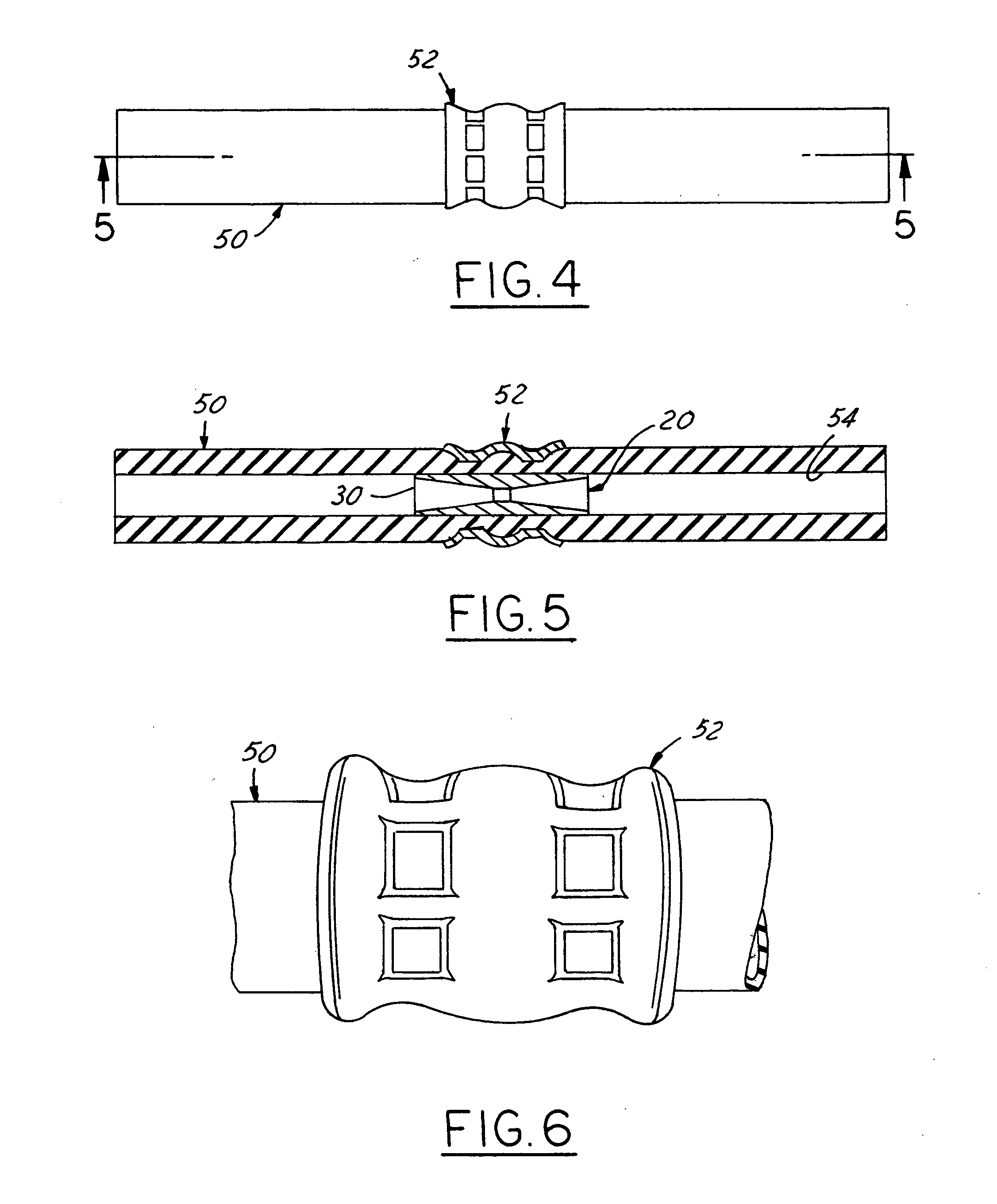
Another problem, unrelated to the noise problem experienced with the current production low pressure side restrictor (often referred to in the trade as a “dogbone”), was hose pinching when the crimp collar location was not correct relative to the dogbone exterior shape of the restrictor.
In such cases, the raised edge of the restrictor sometimes caused hose damage and failure.
Assuming that the “hiss” noise problem was indeed due to the creation of a turbulence condition in the fluid flow just before or after the exit of the restrictor, ancillary problems would be excessive pressure drop and heat generated by such turbulence, as well as potential cavitation wear on the wall of the tubing.
Moreover, these ancillary problems could be present even in the absence of the turbulence reaching a level sufficient to produce the annoying audible “hiss” sound.

Method used


Image

  • Method and apparatus for reduction of fluid-borne noise in hydraulic systems
  • Method and apparatus for reduction of fluid-borne noise in hydraulic systems
  • Method and apparatus for reduction of fluid-borne noise in hydraulic systems

Examples


Embodiment Construction

[0021]FIGS. 1 and 2 illustrate a power steering system restrictor 20 constructed in accordance with a presently preferred first embodiment of the invention. The direction of fluid flow through restrictor 20 is indicated by the arrow FF in FIG. 1. Various dimensional parameters are designated by the dimensional lines and arrows labeled “A through J” and are tabulated hereinafter by way of a working example.

[0022] Restrictor 20 generally comprises a tubular metallic body having a cylindrical exterior surface 21 with an outside diameter (O.D. dimension) designated by reference character “A” in FIG. 1. Resrictor 20 has a central flow-through passage 22 open at its opposite axial ends and constructed in the form of a venturi passage as defined by a shallow tapered inlet passage 24, a relatively short length constant diameter throat passage 26, and a shallow tapered outlet passage 28. Preferably the cross sectional configuration of the interior of the restrictor, as defined by passage se...


PUM


Abstract

Method and apparatus for eliminating turbulence-induced noise in a pulsation-absorbing flexible hose, as in a hydraulic power steering system containing a pressure fluid-feeding pump and a steering gear operated by the pressure fluid discharged from the pump. The hose has a restrictor positioned in the hose bore, and the restrictor has a flow-through bore of smaller diameter than that of the adjacent wall of the hose bore. The flow-through bore has a venturi tube cross section. The restrictor venturi inlet, throat and outlet are designed so as to efficiently conduct fluid therethrough by matching the characteristics of the fluid, the operational pressures, fluid density and other system parameters such that the venturi operates below the lower critical value of the Reynolds number of fluid flow through the restrictor to thereby minimize or eliminate fluid turbulence in the restrictor outlet and / or immediately downstream thereof.

Description

FIELD OF THE INVENTION [0001] This invention relates to noise and / or vibration attenuation apparatus for a system conveying liquid under pressure and to a method of attenuating noise and / or vibration in such a system, particularly in the hydraulic system of the power steering unit of a vehicle. BACKGROUND AND SUMMARY OF THE INVENTION [0002] Fluid-borne noise is commonly present in hydraulic systems powered by pumping apparatus such as gear, vane or piston pumps. Typically, the noise results when pressure waves generated as pump flow ripple encounter system flow impedance. Fluid-borne noise present in a hydraulic system causes mechanical apparatus, such as hydraulic lines, control valves, hydraulic motors, and supporting structural members, to vibrate. In many cases, such vibration is coupled to the atmosphere and is the source of objectionable acoustic noise. It is of course, desirable to attenuate such fluid-borne noise. [0003] Fluid-borne noise reduction apparatus in the high pres...

Claims


Application Information

Patent Timeline
Patent Type & Authority Applications(United States)
IPC IPC(8): B62D5/06F16L55/027
CPCF16L55/027B62D5/062
Inventor KRIEGER, CLIFFORD P.BEATTY, JAMES P.CASTALDI, THOMAS E.DAVIS, MYLES E.SINCLAIR, DARYL A.
Owner COUPLED PRODS
Learn More