
Weighing pan carrier with overload protection device

Inactive Publication Date: 2005-03-03
METTLER TOLEDO GMBH
View PDF15 Cites 11 Cited by
  • Summary
  • Abstract
  • Description
  • Claims
  • Application Information

AI Technical Summary

Benefits of technology

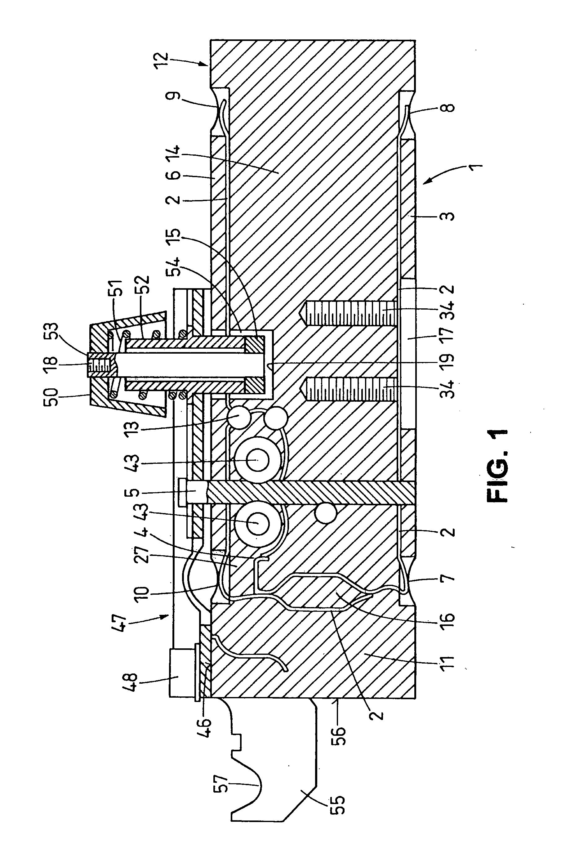
[0013] The safety means that protect the load-receiving device of the weighing cell against the twisting action of a torque prevent the risk of an irreversible deformation of the weighing cell that could be caused by lateral forces occurring as a result of an excessive torque being applied to the weighing pan and subsequently being transmitted to the weighing pan carrier and to the load-receiving portion of the weighing cell in the process of installing a superstructure on the weighing pan, particularly in tightening the screws. The consequences of an irreversible deformation of the weighing cell would manifest themselves at least through errors in the weighing results, and in the worst case through a destruction of the weighing cell.
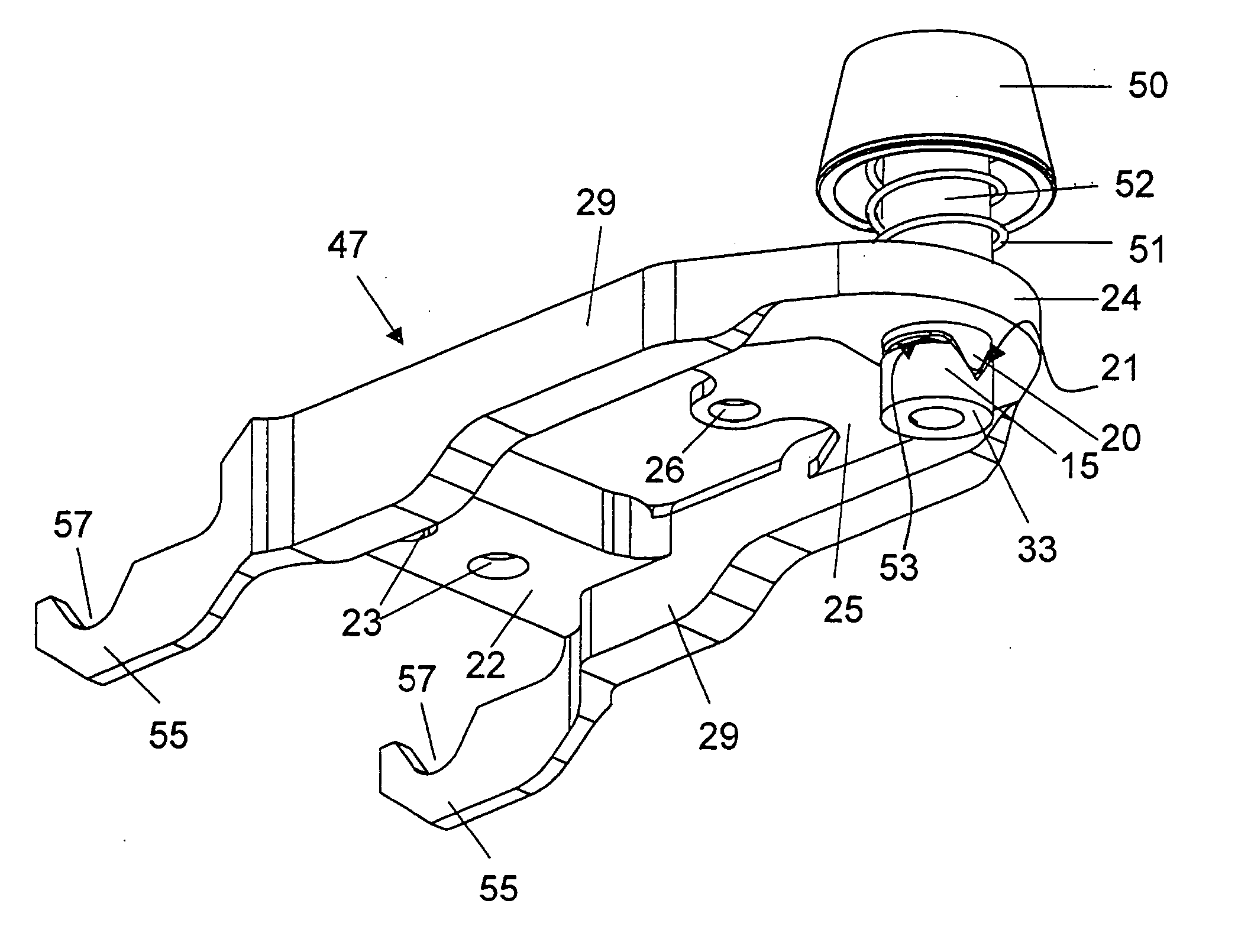
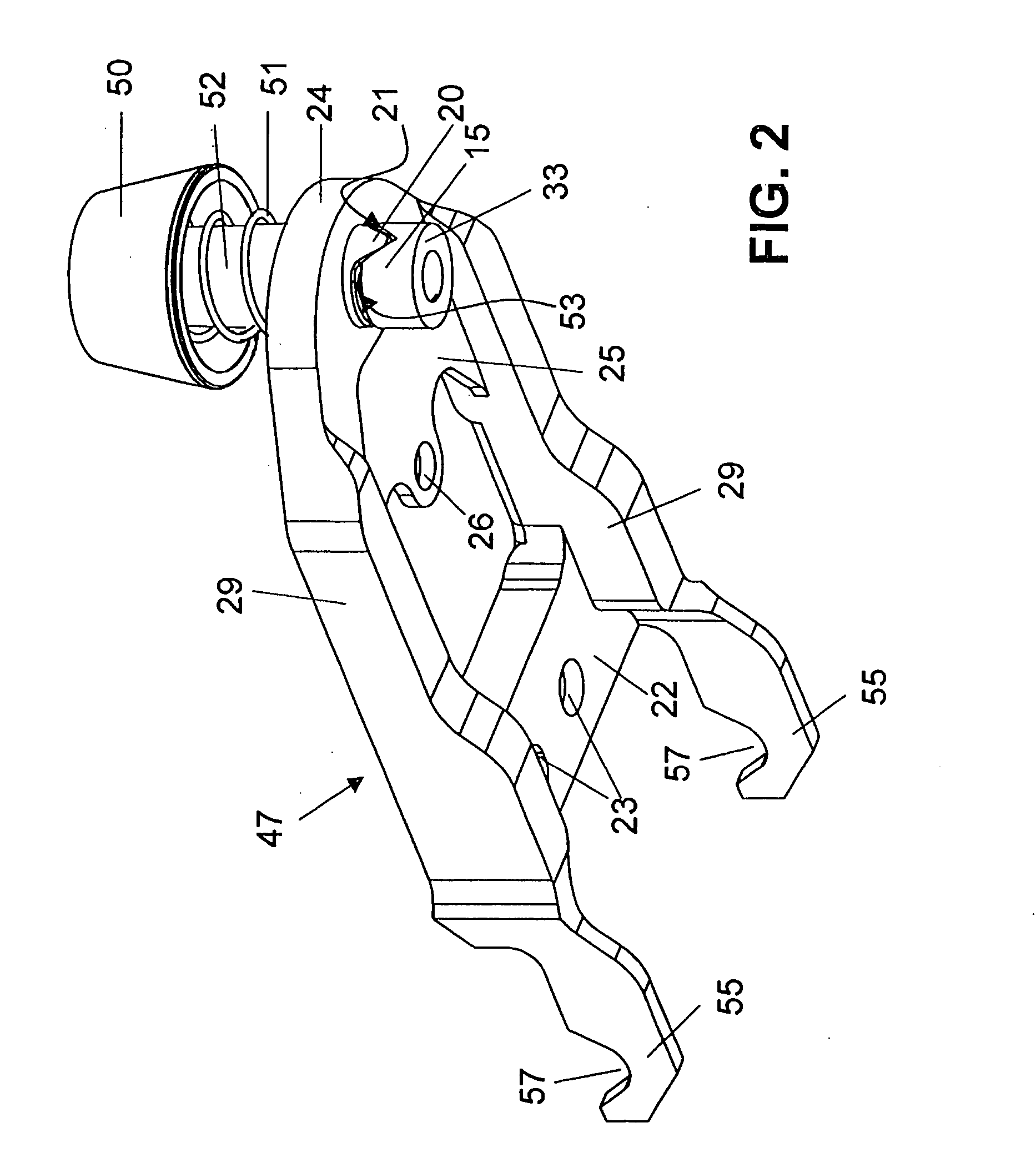
[0014] In a preferred embodiment of the invention, the weighing pan carrier has a seating cone for the weighing pan, and the torque safety feature has an elastic element, in particular a pre-tensioned helix spring, that maintains the engagement between the weighing pan carrier and the seating cone.
[0016] In a special embodiment of the balance for applications where there is a risk that dust and / or spray water could get inside the balance housing, the torque safety feature is configured so that when the seating cone for the weighing pan is uncoupled from the weighing pan carrier, a restraining stop prevents the mutually engaging elements from sliding totally out of engagement.

Problems solved by technology

When an excessive force is directed vertically at the load-receiving portion, for example as a result of an excessive load being put on the weighing pan, the connection releases itself.
When an excessive amount of torque is applied, the two clutch halves release their mutual engagement against the force of the spring.

Method used


Image

  • Weighing pan carrier with overload protection device
  • Weighing pan carrier with overload protection device
  • Weighing pan carrier with overload protection device

Examples


Embodiment Construction

[0029]FIG. 1 represents a sectional view of a weighing cell in a plane that runs parallel to the larger pair of side surfaces of the weighing cell, with the measuring transducer removed. The weighing cell includes a force-transmitting mechanism formed out of a substantially brick-shaped material block 1, where the force-transmitting mechanism consists of material portions of the block that are separated from each other by material-free gaps in the form of narrow linear cuts 2 traversing the material block 1 perpendicular to its main plane. The material portions form a parallelogram linkage with an upper parallelogram guide 6 and a lower parallelogram guide 3, with one parallelogram leg forming a stationary portion 12 and the other parallelogram leg forming the load-receiving portion 11, the latter being vertically movable, guided by concave-shaped flexure pivots 7, 8, 9, 10 which are delimited by material-free portions. A force-transmitting lever 27 is formed by further material por...


PUM


Abstract

A weighing pan carrier (47) for a balance with a weighing pan and with a weighing cell that includes a load-receiving portion (11) and a stationary portion (12) has an overload protection device against excessive vertically directed forces that is releasably engaged with the weighing pan carrier. The weighing pan carrier (47) is fastened to the load-receiving portion (11) of the weighing cell and has on the other hand a fixed connection to the weighing pan. The weighing pan carrier (47) has a torque safety feature, which is integrated in the overload protection device and provides protection against excessive forces acting tangentially on the weighing pan and / or on the weighing pan carrier (47) in a direction perpendicular to the direction of the weighing load.

Description

CROSS REFERENCE TO RELATED APPLICATION [0001] This application is a continuation of application number PCT / IB02 / 04770, filed Nov. 15, 2002, which is expressly incorporated herein.BACKGROUND OF THE INVENTION [0002] The invention relates to a weighing pan carrier for a balance with a weighing pan and a weighing cell, the latter having a load-receiving portion and a stationary portion. The weighing pan carrier is attached to the load-receiving portion of the weighing cell, and an overload protection device is in releasable engagement with the weighing pan carrier. [0003] The overload protection device in a balance has the function of uncoupling the load-receiving device, in particular the weighing pan, from the weighing cell when a maximally permissible load is exceeded, where the load causes a substantially vertical force to act on the weighing pan. As a result, the weighing cell is protected from the effect of excessive, primarily vertically directed forces, which can either be of a ...

Claims


Application Information

Patent Timeline
IPC IPC(8): G01G21/24G01G23/00G01G23/02G01G21/23
CPCG01G23/005
Inventor BURKHARD, HANS-RUDOLPH
Owner METTLER TOLEDO GMBH
Learn More