
RF testing method and arrangement

a technology of electronic devices and testing methods, applied in the direction of electronic circuit testing, measurement devices, instruments, etc., can solve the problems of inability to test, slow analysis, and inability to accept electronic devices, and achieve the effect of accurate testing of electronic devices, simple testing, and convenient us

Inactive Publication Date: 2005-03-03
ELEKTROBIT TESTING OY
View PDF13 Cites 25 Cited by
  • Summary
  • Abstract
  • Description
  • Claims
  • Application Information

AI Technical Summary

Benefits of technology

[0009] The method and arrangement of the invention provide several advantages. By testing the forms of the measurement signals, the behaviour of the electronic device can be tested accurately. Testing is simple, and the signal analysis can be performed with a low processing power. Thus, the testing device will be cheap and easy to use. The total testing time can also be kept short because the analysis of the measured signal can be performed simultaneously with the measurement.

Problems solved by technology

If the limits are not met, the electronic device is not acceptable.
There are, however, problems related to the testing.
The analysis is slow and it has to be carried out after the measurements.
Although the testing systems can be rather complex, the versatility is limited and analysis requires a lot of processing power, which unnecessarily increases the delay in receiving the results from the test.
Further, since the analysis does not properly take into account the forms of the measurement signals, pieces of information are lost and certain latent defects may be difficult to detect or they may remain completely undetected.

Method used


Image

  • RF testing method and arrangement
  • RF testing method and arrangement
  • RF testing method and arrangement

Examples


Embodiment Construction

[0017] The present solution is suitable for testing an electronic device. The electronic device may also comprise optoelectronic components. The device may be such as a phone, a mobile phone, a computer, a modul or a card of a computer (such as PCMCIA), digital camera, PDA, a semiproduct etc., but the present solution is not restricted to these, however.

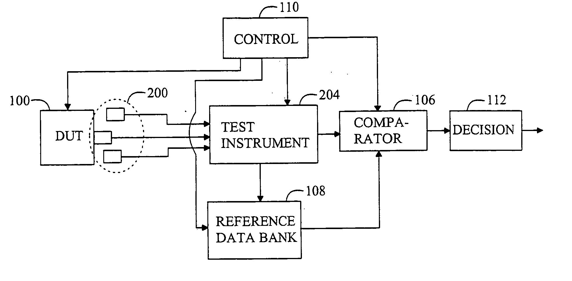
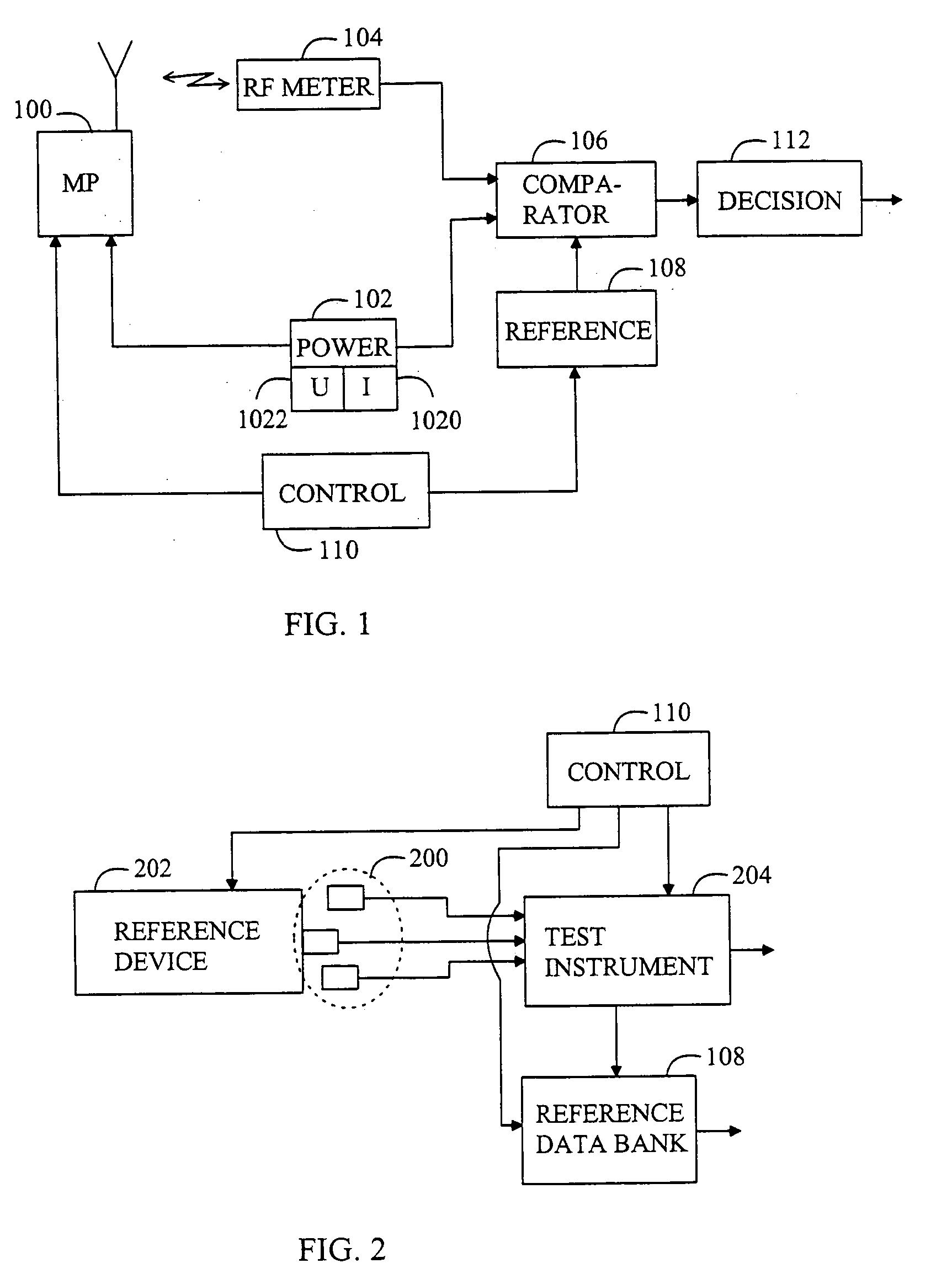
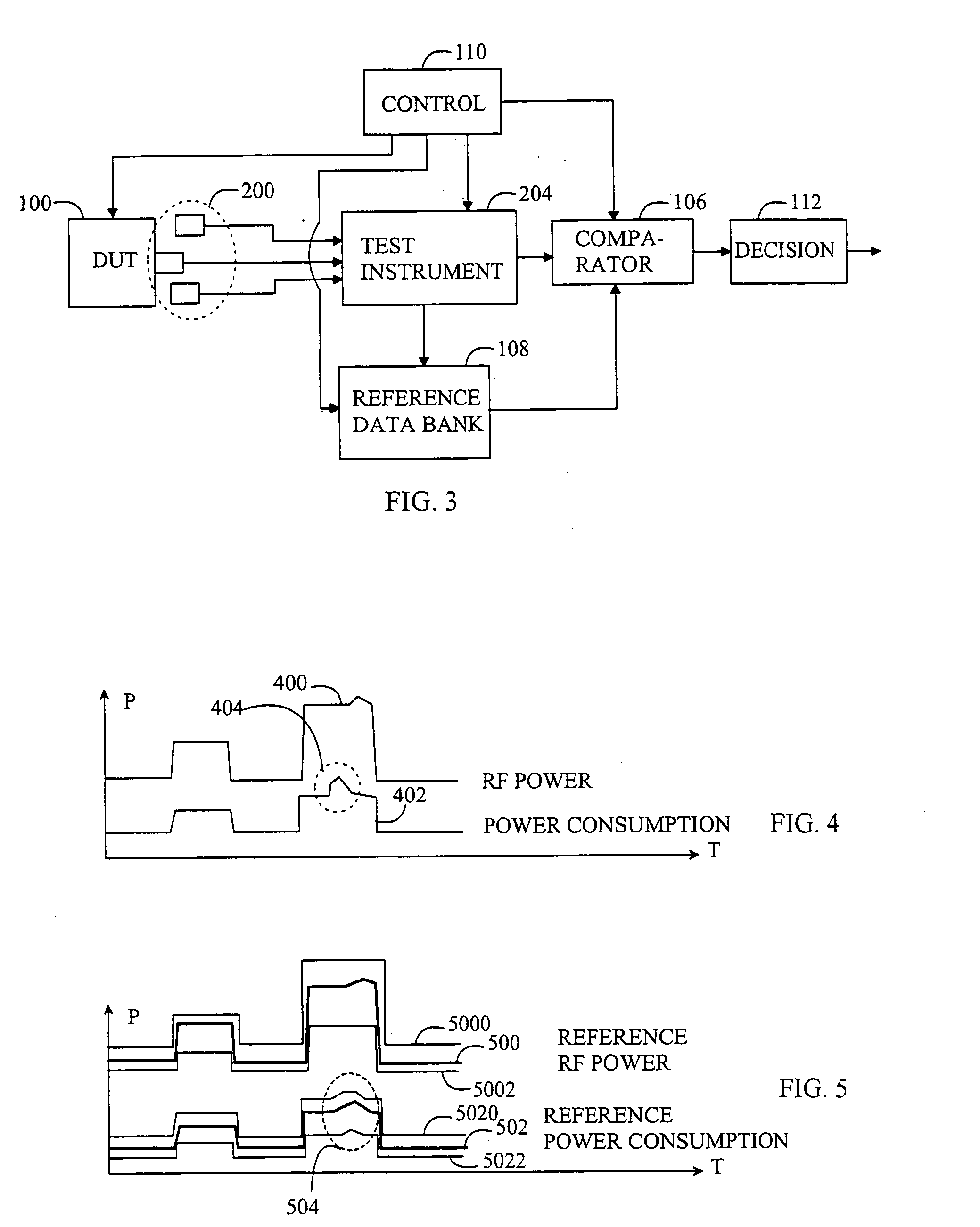
[0018]FIG. 1 shows a basic measurement arrangement in which the electronic device 100 is assumed to be a mobile phone. The electronic device 100 is placed in a testing arrangement, which can comprise a power supply 102 with meters 1020, 1022 for measuring voltage and current fed to the electronic device 100, a sensor 104 for measuring at least one signal output by the electronic device 100, a comparator 106 for comparing at least one measurement signal and at least one reference signal, a reference supply 108 for supplying at least one reference signal, a controller 110 and a decision unit 112. Both the meters 1020, 1022 and the sen...


PUM


Abstract

An RF testing method and arrangement of an electronic device utilize sensors for measuring the electronic device under test in conjunction with production of the electronic devices. A comparator performs a comparison between measurement signals and corresponding reference signals from a reference supply and a decision unit determines defectiveness of the electronic device based on the comparison.

Description

FIELD [0001] The invention relates to RF testing of an electronic device in conjunction with the production. BACKGROUND [0002] Testing an electronic device, for example such as a mobile phone, is of vital importance for ensuring delivery of a correctly operable device to a customer. One of the most important properties to test is the RF operation (Radio Frequency). A test can be performed on a complete electronic device at the end of the production line, or a circuit board or a component can be tested separately. During testing, measurement signals from the electronic device are recorded and the measurement signals are then analysed using various analysis algorithms to observe whether the values of the measurement signals fall within desired limits, which are usually manually fed to the testing system. If the values of the measurement signals stay within the limits, the electronic device is acceptable independent of the variation of the measurement signals within the limits. If the ...

Claims


Application Information

Patent Timeline
Patent Type & Authority Applications(United States)
IPC IPC(8): G01R31/302
CPCG01R31/302G01R31/002
Inventor KINNUNEN, JOUKONYKANEN, HEIKKIVALTANEN, JUHAKURSULA, MIKKO
Owner ELEKTROBIT TESTING OY
Learn More