Molding mold, substrate for optical disc, and optical disc

a technology for optical discs and molds, which is applied in the field of molds, substrates for optical discs, and optical discs, can solve the problems of affecting so as to improve the accuracy of optical disc thickness, and reduce the occurrence of burrs

Inactive Publication Date: 2005-03-03
TDK CORPARATION
View PDF4 Cites 22 Cited by
  • Summary
  • Abstract
  • Description
  • Claims
  • Application Information

AI Technical Summary

Benefits of technology

[0010] It is a primary object of the present invention to provide a molding mold, for molding a mold substrate for an optical disc, constructed to restrain an occurrence of a burr, etc. adversely affecting the optical disc and to enable an improvement of accuracy of thickness of the optical disc made by using the mold substrate.
[0011] It is another object of the present invention to provide a substrate for an optical disc that is constructed to enable the thickness accuracy to be improved.
[0012] It is a further object of the present invention to provide an optical disc with the improved thickness accuracy.

Problems solved by technology

In a structure shown in FIG. 11A, however, the collar portion H1 of the holder protrudes into a cavity of the molds, and hence, as shown in FIG. 11B, a recessed portion A1 is formed in a mold substrate A. Especially when forming a variety of functional layers on this mold substrate by a spin coat method, this large recessed portion A1 (its depth is on the order of 0.2 mm to 0.3 mm) greatly hinders the spread of materials composing the functional layers, thereby inducing inconvenience such as unevenness of coating, coating streaks, or the like.
The burr B1 also causes inconvenience to the formation of the functional layers that involves employing the same spin coat method as the above, and another inconvenience arises in the case of bonding a different substrate or the like onto the face formed with the burr.
For instance, in the case of forming, e.g., a light transmissive layer by the spin coat method in manufacturing the optical disc such as a Blu-ray disc (using blue laser beams) expected as a next generation high-density recording medium at the present, if there exists much of the recessed portion A1 (particularly as a stepped portion close to the outer periphery becomes larger and as an inclination of the wall get steeper) or the burr B1 on the mold substrate, as explained above, a problem also arises, wherein this causes a decline of spin coating property and occurrences of the coating streaks and the unevenness of the thickness.
It is, however, impossible to restrain the occurrence of the burr by all means.
A protruded configuration can be provided in terms of the level relationship, however, in the case of manufacturing, e.g., a 2- or more-tiered disc spacer layer by use of a 2P method, there is a problem that the level (stepped portion) is required to be adjusted equal to or smaller than the thickness of this spacer layer, and the requirement of accuracy of the thickness becomes more strict.

Method used


Image

  • Molding mold, substrate for optical disc, and optical disc
  • Molding mold, substrate for optical disc, and optical disc
  • Molding mold, substrate for optical disc, and optical disc

Examples


Embodiment Construction

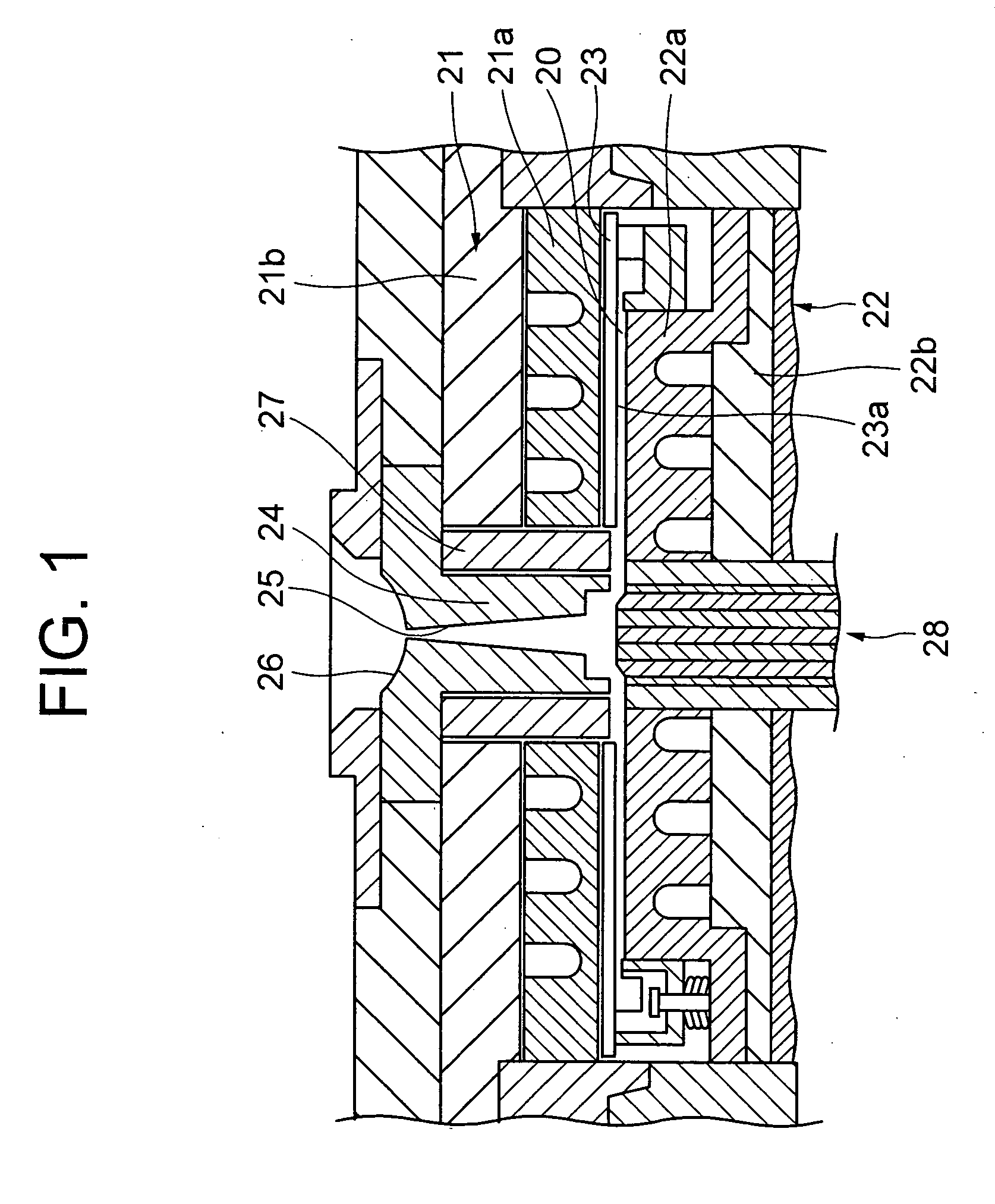
[0058] A best mode for carrying out the present invention will hereinafter be described with reference to the drawings. FIG. 1 is a sectional view of a principal portion of a molding mold assembly according to the present embodiment. This molding mold assembly serves to mold a plastic mold substrate for optical discs such as a CD, a DVD, a Blu-ray disc and so on.

[0059] The molding mold assembly shown in FIG. 1 includes a fixed mold 21 and a movable mold 22. The fixed mold 21 has a fixed mirror surface portion 21a, a fixed mold plate 21b, a holder member 27 disposed in the vicinity of the center, and a sprue bush 24 disposed at the center on the side of an inside diameter of the holder member 27. Further, the movable mold 22 has a movable mirror surface portion 22a, a movable mold plate 22b and an ejection member 28 driven upwards as viewed in FIG. 1 in order to extract a mold product when in mold releasing after being molded.

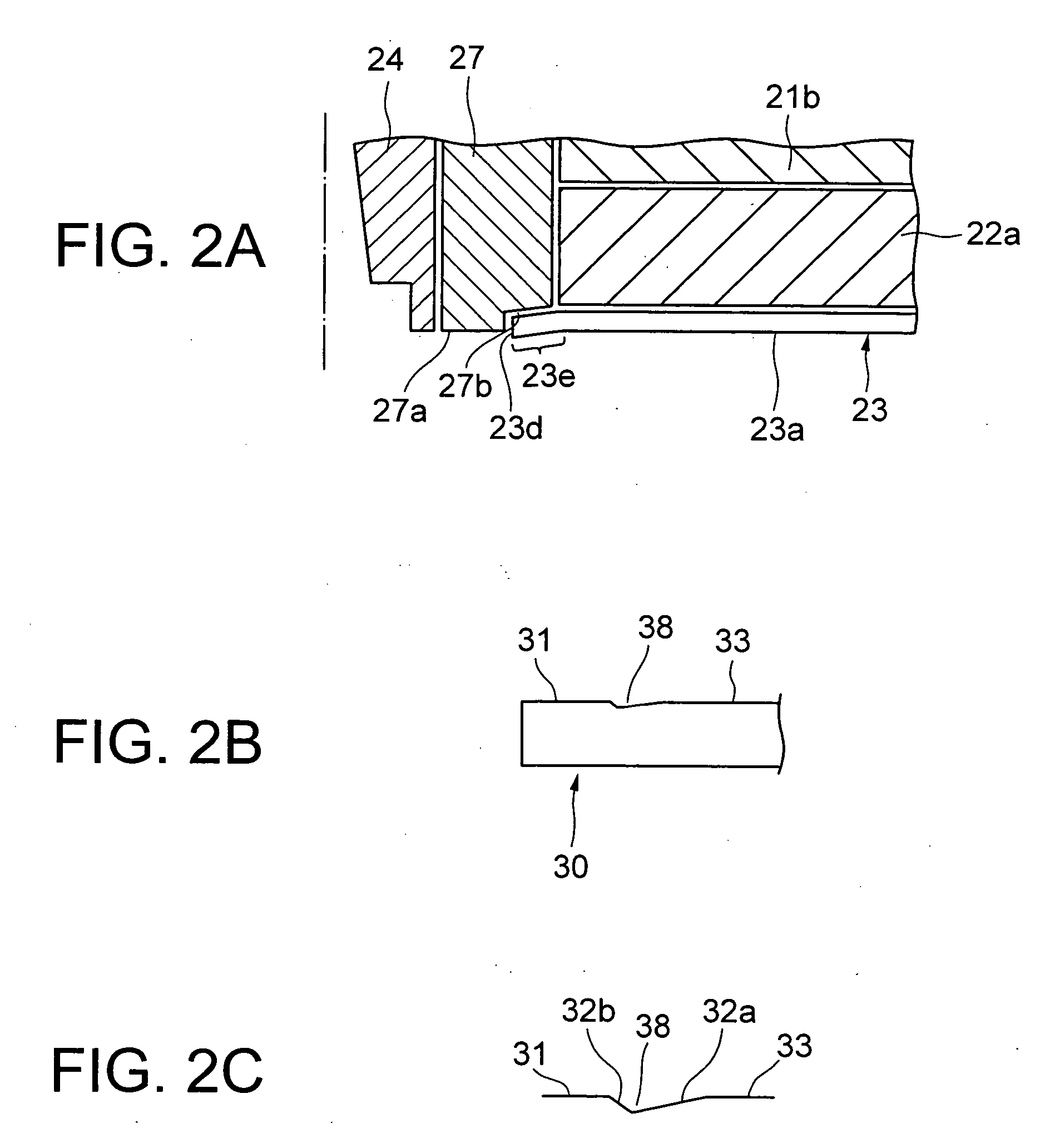
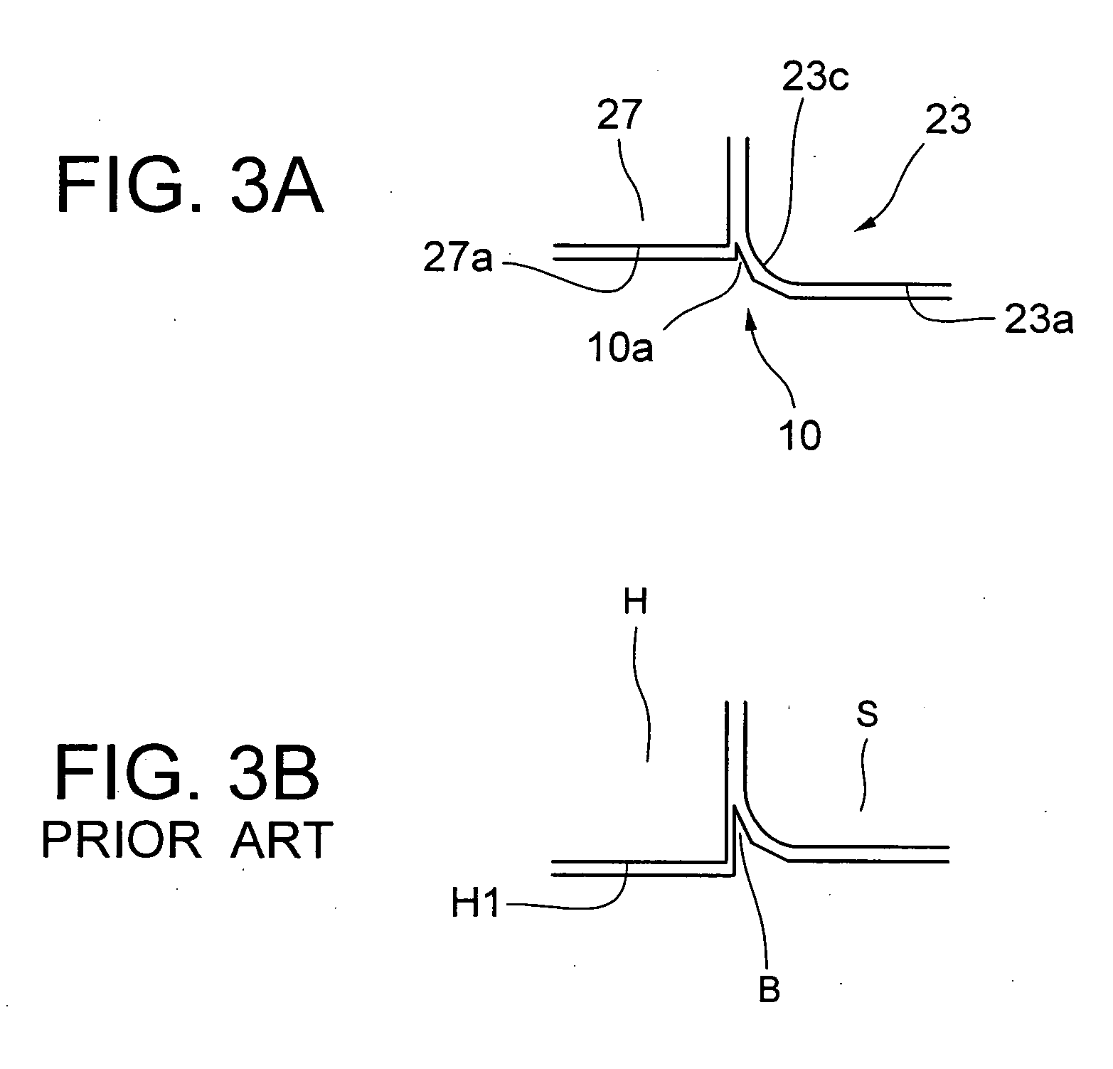
[0060] A stamper 23 is composed of nickel, etc., in a pl...


PUM

PropertyMeasurementUnit
depthaaaaaaaaaa
heightaaaaaaaaaa
diameteraaaaaaaaaa

Abstract

A molding mold assembly is provided, for molding a mold substrate for an optical disc, to reduce an occurrence of burrs, etc. adversely affecting the optical disc and to improve accuracy of thickness of the optical disc made by the mold substrate. A substrate for an optical disc is provided that is capable of improving the accuracy of the thickness, as well as an optical disc with the improved accuracy of the thickness. The molding mold assembly is constructed such that a cavity for molding the mold substrate for the optical disc is configured, a stamper for transferring a hyperfine pattern onto the mold substrate is attached to the mold assembly so that a vicinal part of an innermost periphery portion of the stamper protrudes towards the cavity, and a face formed by a mold member configuring an inner peripheral portion of the mold substrate is substantially flush with an information area face on which the hyperfine pattern has been transferred.

Description

INCORPORATION BY REFERENCE [0001] The present application claims priority under 35 U.S.C. §119 to Japanese Patent Application No. 2003-300799 filed on Aug. 26, 2003. The content of the application is incorporated herein by reference in its entirety. BACKGROUND OF THE INVENTION [0002] 1. Field of the Invention [0003] The present invention relates to a molding mold for molding an optical disc mold substrate for manufacturing an optical disc, the substrate for the optical disc, and the optical disc. [0004] 2. Description of the Prior Art [0005] Conventional molding molds for molding an optical disc are constructed such that a stamper formed with hyperfine signal pits is held at its an inner peripheral portion within the molding molds, in which case an inner peripheral portion S1 of a stamper S is, as shown in FIG. 11A, pressed and thus held by use of a holder H including a collar portion H1 having a larger diameter than an inside diameter of the stamper. Further, as shown in FIG. 12A, ...

Claims


Application Information

Patent Timeline
Patent Type & Authority Applications(United States)
IPC IPC(8): B29C33/42B29C45/26B29D17/00B29L17/00G11B7/24G11B7/24047G11B7/24056G11B7/26
CPCB29C33/424B29C33/428B29C45/2632B29L2017/005B29D17/00B29D17/005B29C2045/2667
Inventor YAMAGA, KENJIKOMAKI, TSUYOSHI
Owner TDK CORPARATION
Why Eureka
Try Eureka