Dust collection system for a belt sander
- Summary
- Abstract
- Description
- Claims
- Application Information
AI Technical Summary
Benefits of technology
Problems solved by technology
Method used
Image
Examples
Embodiment Construction
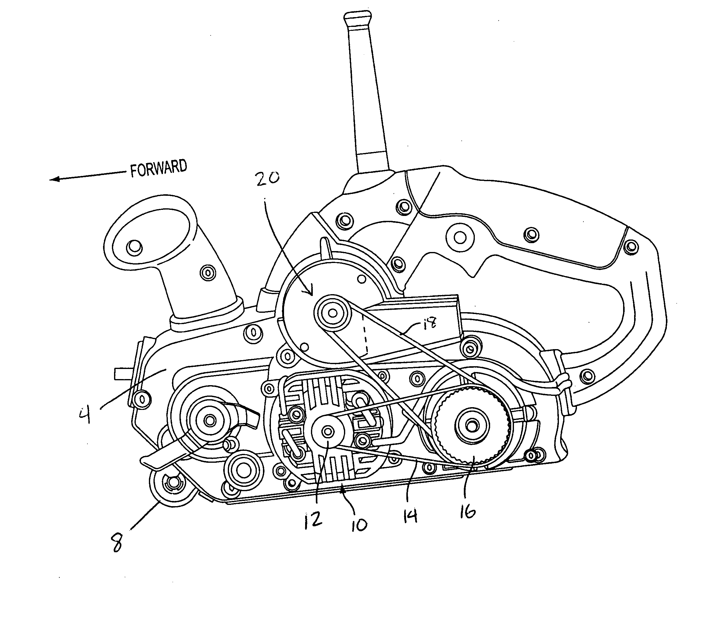
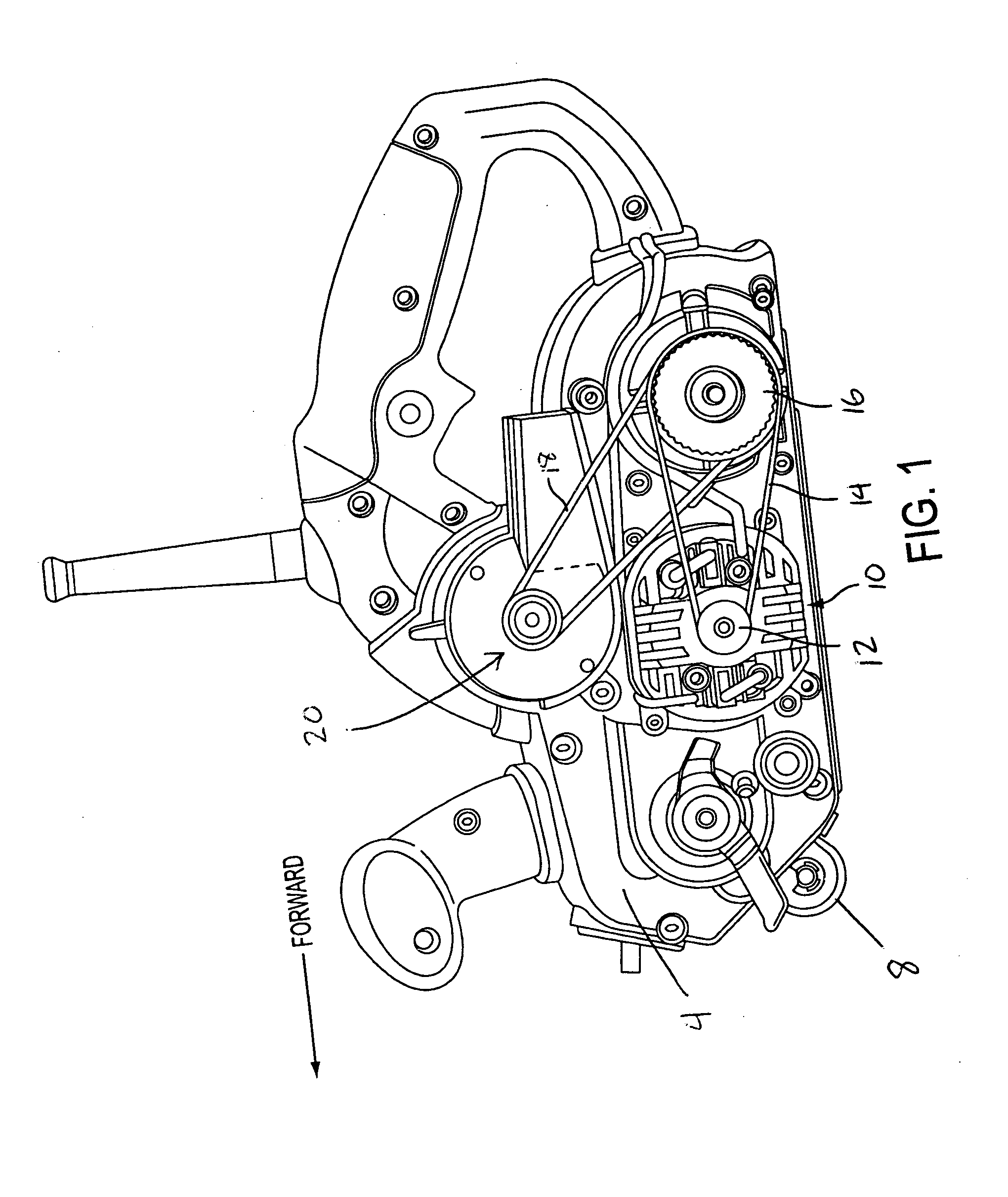
[0037] With reference to the accompanying FIGS. 1, 2, 3, and 4, motor assembly 10 is transversely mounted between the rearwardly located drive roller 9 and the front roller assembly 8. The motor output shaft, which extends through an opening in gear case cover 4, ends in drive pulley 12.
[0038] Drive pulley 12 pulls drive belt 14. Drive belt 14 turns driven pulley 16. Driven pulley 16, through gearing not shown, turns rear drive roller 9. A second portion of driven pulley 16 pulls dust collection fan belt 18, which powers a dust collection fan 20 that is located on an upper portion of gear case cover 4. In the preferred embodiment shown, fan belt 18 is an o-ring.
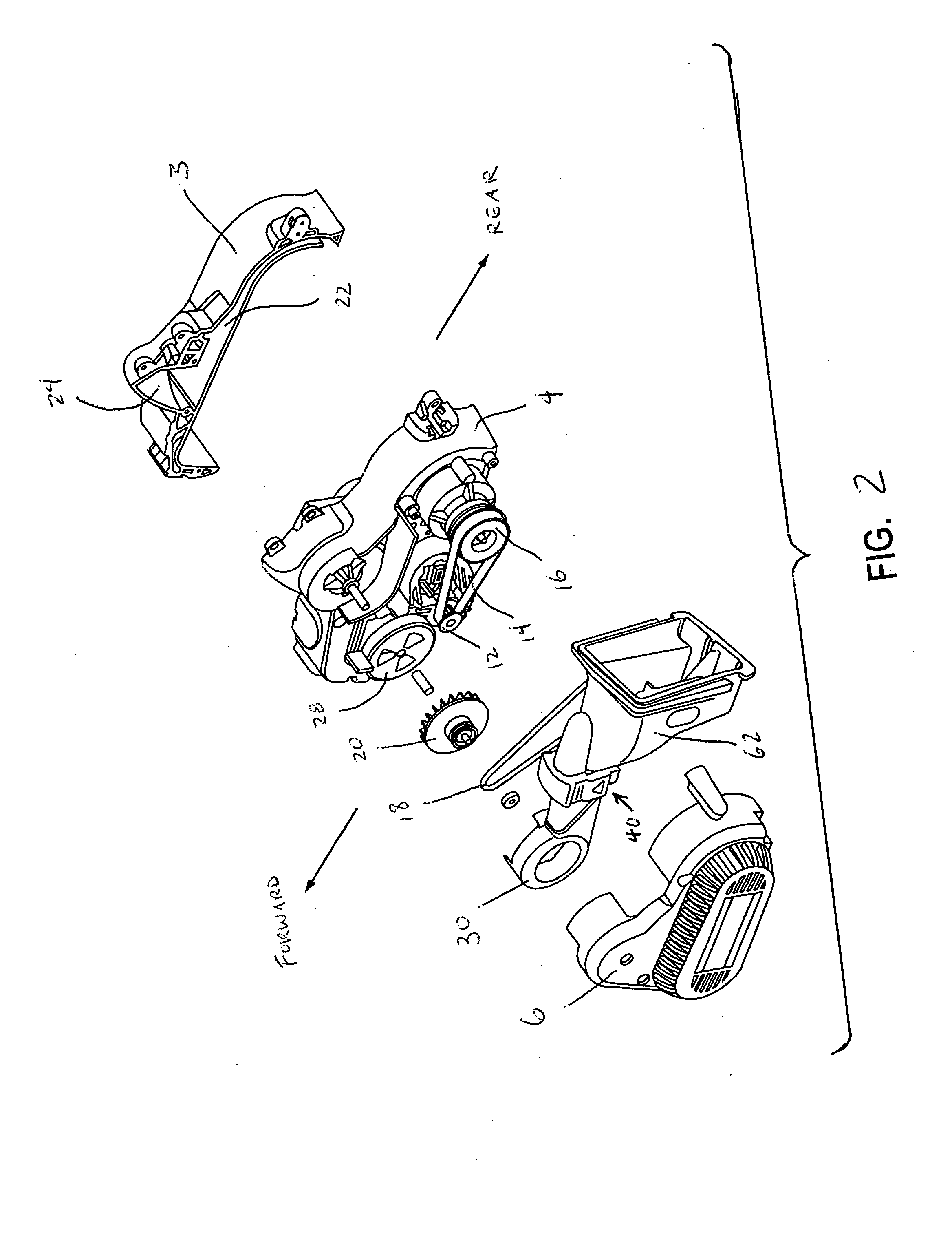
[0039] With particular reference to FIGS. 2-4, the left-hand / outward side of the gear case cover 4 is covered by belt cover / housing 6, which encloses the pulleys 12 and 16 and belts 14 and 18. Completing the frame / superstructure of the sander is the right side housing 3.
[0040] With additional reference to FIGS. 5-7, the su...
PUM
| Property | Measurement | Unit |
|---|---|---|
| Volume | aaaaa | aaaaa |
| Flexibility | aaaaa | aaaaa |
| Transmission | aaaaa | aaaaa |
Abstract
Description
Claims
Application Information
 - R&D
- Intellectual Property
- Life Sciences
- Materials
- Tech Scout
- Unparalleled Data Quality
- Higher Quality Content
- 60% Fewer Hallucinations
Browse by: Latest US Patents, China's latest patents, Technical Efficacy Thesaurus, Application Domain, Technology Topic, Popular Technical Reports.
© 2025 PatSnap. All rights reserved.Legal|Privacy policy|Modern Slavery Act Transparency Statement|Sitemap|About US| Contact US: help@patsnap.com


