Methods for marking a biopsy site

a biopsy site and marking technology, applied in the field of marking a biopsy site, to achieve the effect of visualizing the marker

Inactive Publication Date: 2005-03-03
DEVICOR MEDICAL PROD
View PDF99 Cites 120 Cited by
  • Summary
  • Abstract
  • Description
  • Claims
  • Application Information

AI Technical Summary

Benefits of technology

[0016] This invention solves the problems noted above by providing an implantable device which is particularly adapted to mark the location of a biopsy or surgery for the purpose of identification. The device is remotely delivered, preferably percutaneously. Visualization of the marker is readily accomplished using various state of the art imaging systems. Using the invention, it is possible to permanently mark the location or margins of a lesion or other tissue site, prior to removing or sampling same. The markers function to provide evidence of the location of the lesion after the procedure is completed, for reference during future examinations or procedures.

Problems solved by technology

Since, with remote delivery (e.g. percutaneously) direct visual access is not possible, an aided visualization device is used, such as an imaging system, an endoscope, or the like.
However, in other embodiments, the marking device is self contained, having a means itself for obtaining entry to the body, and being guided by a commercially available guidance system, such as a stereotactic guidance system.

Method used


Image

  • Methods for marking a biopsy site
  • Methods for marking a biopsy site
  • Methods for marking a biopsy site

Examples


Embodiment Construction

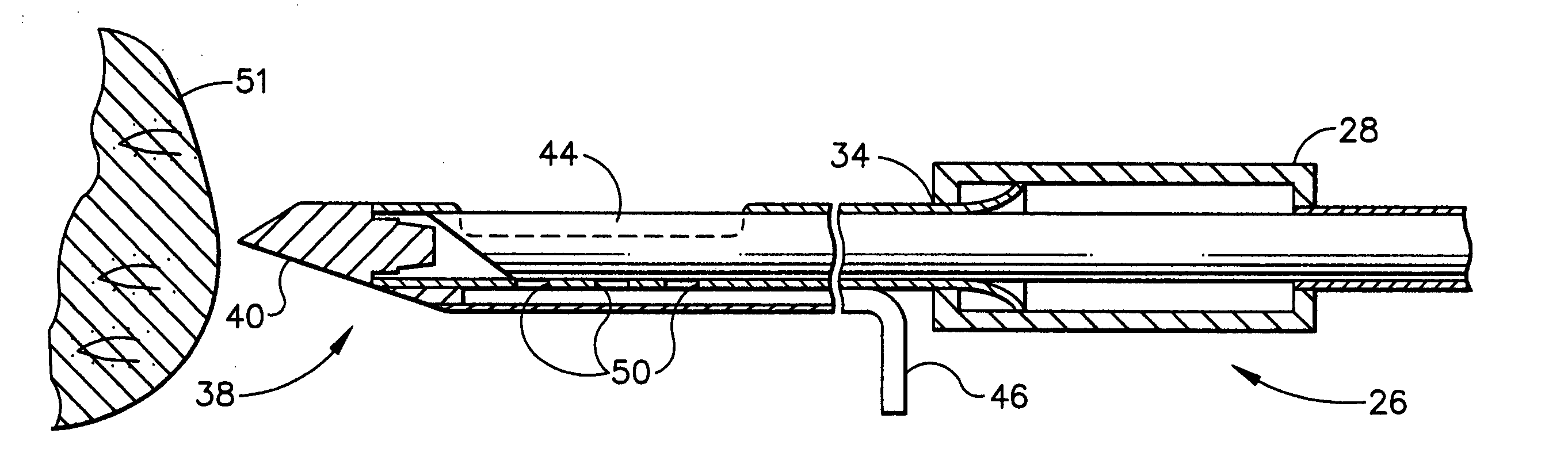
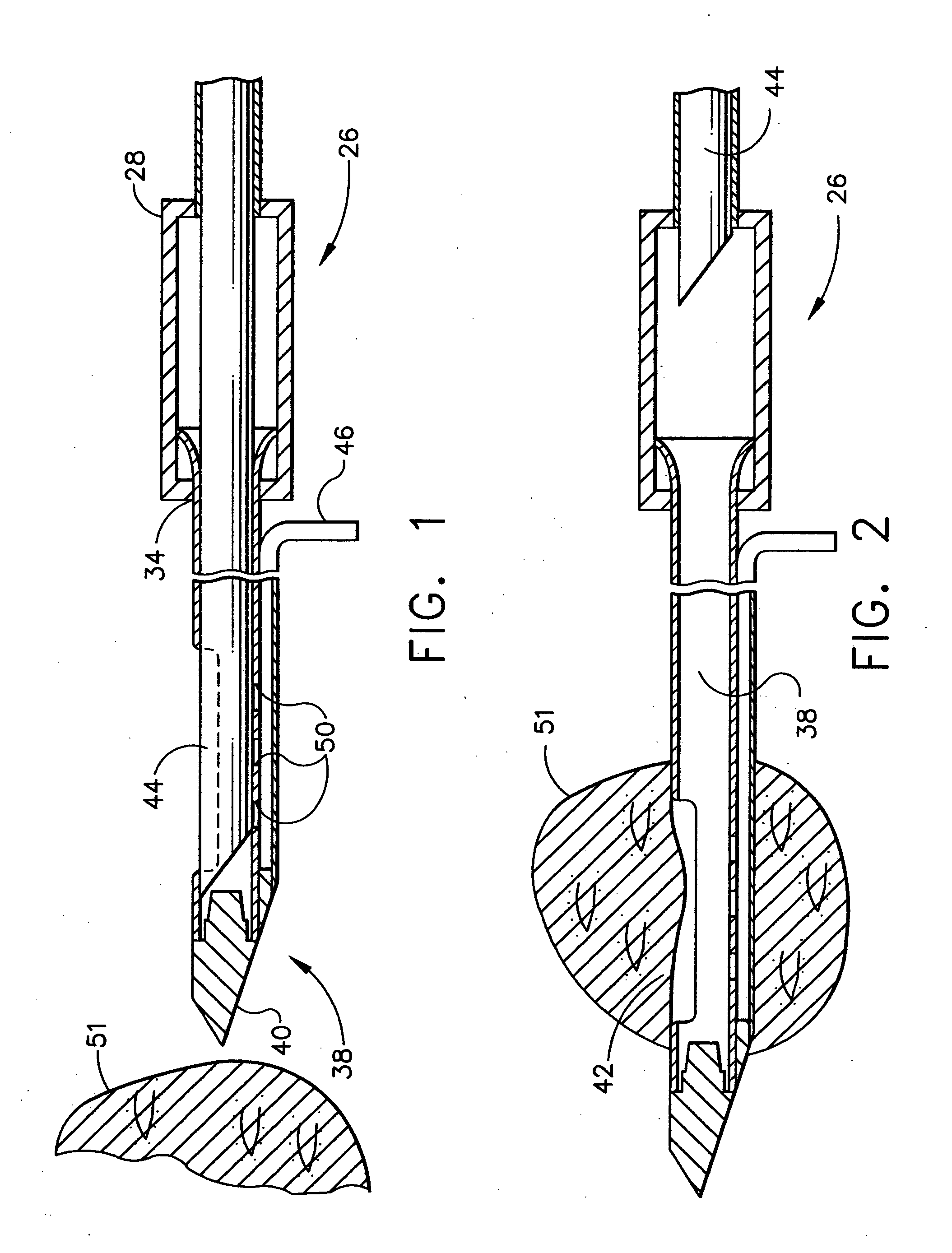
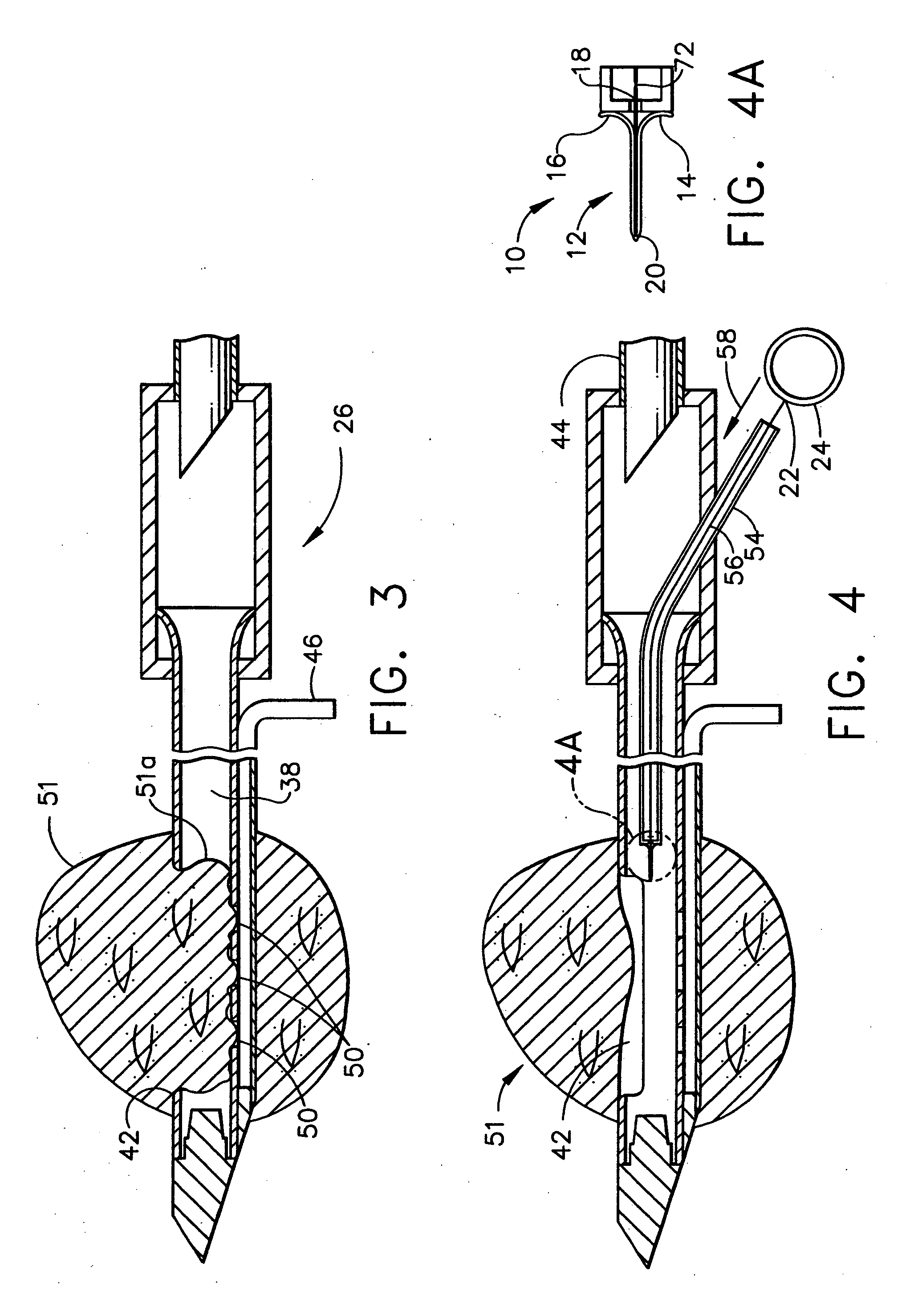
[0042] Now with more particular reference to the drawings, FIGS. 4-8 illustrate sequentially the deposit of a marker into a desired tissue location, utilizing a preferred embodiment of the invention. Specifically, the marking instrument 10 comprises a marker element 12 which includes an umbrella end comprising a pair of attachment members or wings 14 and 16, and a center wire 18. All three wires 14, 16 and 18 are joined at the distal end 20 of the center wire 18, preferably by welding. At the proximal end 22 of the center wire is a deployment actuator or pull ring 24, which is preferably attached by welding or brazing.

[0043] To place the marker element 12 at a desired location, a biopsy needle or gun is preferably used, though other known delivery means could be used as well. For example, the stand-mounted biopsy instrument described in U.S. patent application Ser. No. 08 / 217,246, previously incorporated by reference into this application, is a preferred instrument for introducing ...


PUM


Abstract

Implantable devices and methods of use are disclosed for marking the location of a biopsy or surgery for the purpose of identification. The methods include providing a biodegradable radiodense implant and taking a tissue sample from a biopsy site within a breast of a patient. The biodegradable implant is then positioned at the biopsy site. The tissue sample is tested and the biopsy site is then relocated. In one embodiment, the entire implant is radiodense. In another embodiment, the entire implant is biodegradable. Methods of using a biodegradable implant having a radiodense material and a biodegradable implant that is visible using an imaging system are also included.

Description

[0001] This is a continuation of U.S. application Ser. No. 10 / 630,883, filed Jul. 30, 2003, which is a divisional of U.S. application Ser. No. 10 / 213,638, filed Aug. 7, 2002, which is a divisional of U.S. application Ser. No. 09 / 954,646, filed Sep. 18, 2001, which is a continuation of U.S. application Ser. No. 09 / 776,125, filed Feb. 2, 2001, which is a continuation of U.S. application Ser. No. 08 / 858,389, filed May 19, 1997, now issued as U.S. Pat. No. 6,228,055, which is a continuation of U.S. application Ser. No. 08 / 308,097, filed Sep. 16, 1994, now abandoned. All of the above patents and applications are expressly incorporated herein by reference in their entirety.BACKGROUND OF THE INVENTION [0002] This invention relates to methods and devices for marking and defining particular locations in human tissue, and more particularly relates to methods and devices for permanently defining the location and margins of lesions detected in a human breast. [0003] It is desirable and often ne...

Claims


Application Information

Patent Timeline
Patent Type & Authority Applications(United States)
IPC IPC(8): A61B10/02A61B10/00A61B17/00A61B19/00
CPCA61B10/0275A61B10/0283A61B19/54Y10T24/4501A61B2019/5408A61B2019/5487A61B2017/00004A61B90/39A61B2090/3908A61B2090/3987
Inventor FOERSTER, SETH A.BURBANK, FRED H.RITCHART, MARK A.ZERBOUNI, ELIAS A.
Owner DEVICOR MEDICAL PROD
Why Eureka
Try Eureka