Smart physiologic parameter sensor and method

a physiologic parameter and sensor technology, applied in the field of medical instruments, to achieve the effect of convenient disposal and replacement, and low cos

Inactive Publication Date: 2005-03-03
CONERO RONALD S +1
View PDF47 Cites 51 Cited by
  • Summary
  • Abstract
  • Description
  • Claims
  • Application Information

AI Technical Summary

Benefits of technology

In a second aspect of the invention, an improved sensor housing assembly is disclosed. In one exemplary embodiment, the housing assembly comprises first and second housing elements which are fabricated from a low cost polymer and which include recesses containing the ultrasonic and pressure transducer elements, respectively. The first housing element is adapted to removably receive the second such that the active faces of the ultrasonic and pressure transducer elements are substantially aligned when the housing elements are assembled, and the second housing element (and associated pressure transducer with EEPROM) can be readily disposed of and replaced by the user when required without having to replace or dislocate the first housing element. In a second embodiment, the first housing element is also made optionally removable from the sensor assembly such that the user may optionally replace just the pressure transducer / EEPROM, the ultrasonic transducer(s), or both as desired.

Problems solved by technology

Furthermore, the host system is programmed such that the sensor assembly will be rejected and rendered unusable by the host if certain portions of the aforementioned data do not meet specific criteria.

Method used


Image

  • Smart physiologic parameter sensor and method
  • Smart physiologic parameter sensor and method
  • Smart physiologic parameter sensor and method

Examples


first embodiment

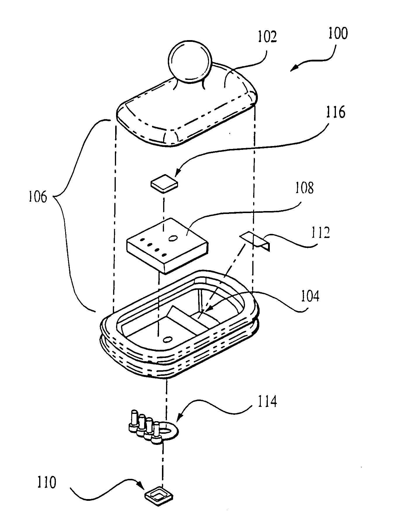
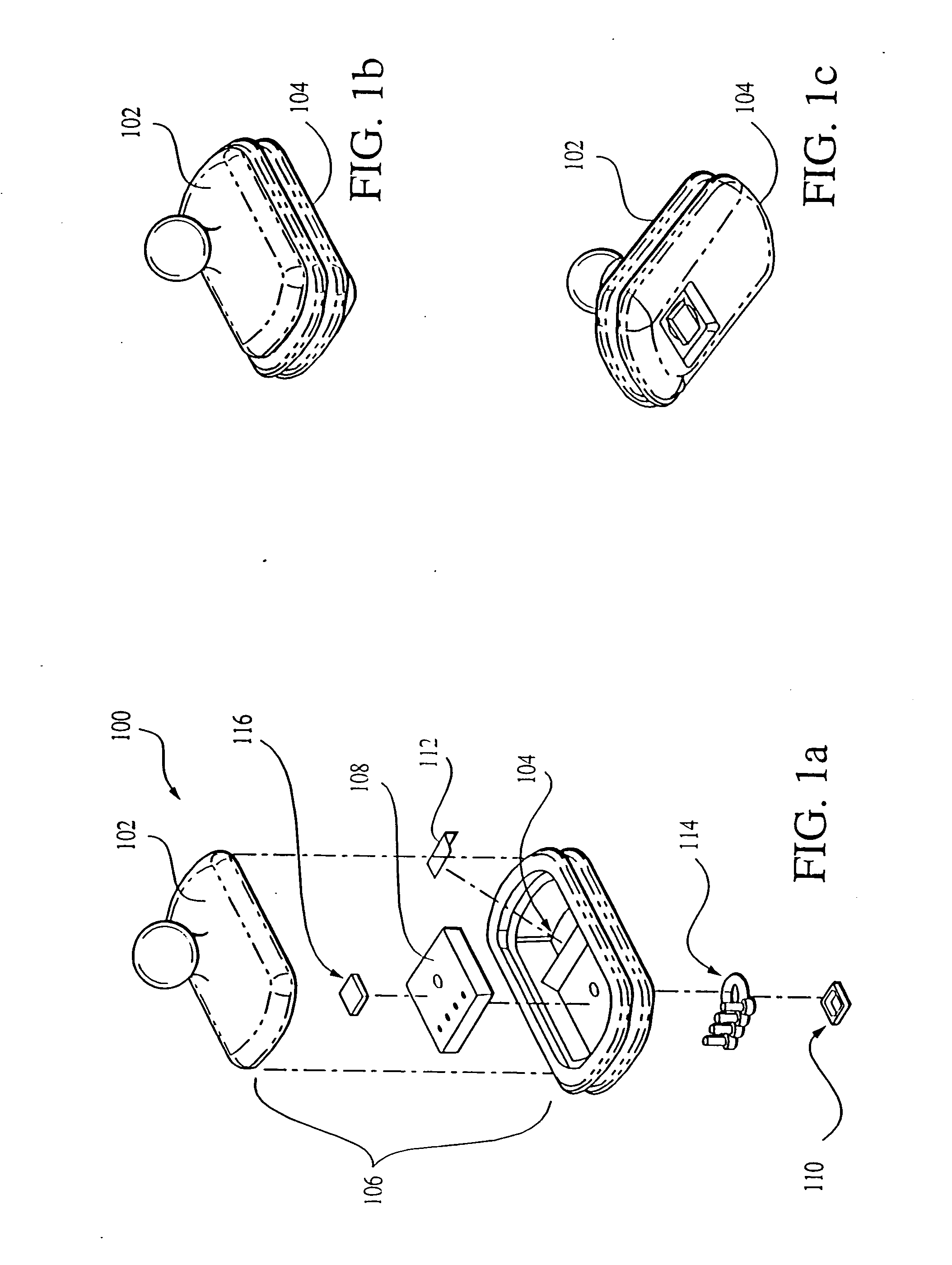
Referring now to FIGS. 1a-1c, the smart sensor assembly 100 of the present invention is described. As shown in FIGS. 1a-1c, the sensor assembly 100 of this embodiment comprises a cover 102 and main sensor housing 104 which are mated together to form the sensor body 106. The shape of the cover 102 and sensor housing 104 is generally that of an elongate rectangle, although it will be recognized that other shapes may be used. A mounting element 107 is formed in the cover 102 to permit, inter alia, positional control of the assembly 100 by the local controller assembly 444 (FIG. 4), as well as an electrical penetration (not shown) for providing power for and data communication with the assembly 100. In the illustrated embodiment, the mounting element is generally spherical or ball-shaped to permit the assembly to couple to the applanation mechanism 407 and operate in a variety of orientations with respect to the local controller 444, although other arrangements (such as universal joints...

second embodiment

FIG. 5 illustrates the physiologic parameter measurement apparatus of the present invention. In the embodiment of FIG. 5, the system 500 further includes a radio frequency (RF) transceiver chip 504 and associated processing of the type well known in the art for transmitting the information generated by the transducers elements 510, 512 and stored within the storage device 518 to the host device via an associated antenna 506 located on the local control assembly 507 and receiver 508 located on the analysis and display device 523. The antenna 506 and receiver 508 ideally comprise transponders, thereby enabling two-way communication between the local control assembly 507 and the analysis and display unit 523.

In the configuration of FIG. 5, the need for wiring or conductors communicating the electrical signals between the local control assembly 507 and the remote analysis and display unit 523 is advantageously obviated, thereby allowing the patient additional mobility during blood pres...


PUM


Abstract

A sensor assembly used for the measurement of one or more physiologic parameters of a living subject which is capable of storing both data obtained dynamically during use as well as that programmed into the device. In one embodiment, the sensor assembly comprises a disposable combined pressure and ultrasonic transducer incorporating an electrically erasable programmable read-only memory (EEPROM), the assembly being used for the non-invasive measurement of arterial blood pressure. The sensor EEPROM has a variety of information relating to the manufacture, run time, calibration, and operation of the sensor, as well as application specific data such as patient or health care facility identification. Portions of the data are encrypted to prevent tampering. In a second embodiment, one or more additional storage devices (EEPROMs) are included within the host system to permit the storage of data relating to the system and a variety of different sensors used therewith. In a third embodiment, one or more of the individual transducer elements within the assembly are made separable and disposable, thereby allowing for the replacement of certain selected components which may degrade or become contaminated. Methods for calibrating and operating the disposable sensor assembly in conjunction with its host system are also disclosed.

Description

BACKGROUND OF THE INVENTION 1. Field of the Invention The present invention relates to the field of medical instrumentation, specifically the use of electronic storage devices for storing and retrieving data relating to, inter alia, particular instruments or patients. 2. Description of Related Technology The ability to readily measure various physiologic parameters associated with a living subject, such as arterial blood pressure or ECG, is often critical to providing effective care to such subjects. Typically, under the prior art, measurement of such parameters is accomplished using a system comprising a host device such as a portable or semi-portable monitoring station that is used in conjunction with a replaceable / disposable probe or sensor assembly, the latter being in direct contact with the subject and measuring the physical parameter (or related parameters) of interest. Such replaceable and disposable sensor assemblies are highly desirable from the standpoint that the ris...

Claims


Application Information

Patent Timeline
Patent Type & Authority Applications(United States)
IPC IPC(8): A61B5/00A61B5/0215A61B8/00A61B8/06
CPCA61B5/00A61B5/0002A61B5/02158A61B5/1112A61B5/6843A61B8/00A61B2562/08A61B2018/00178A61B2018/00988A61B2560/0252A61B2560/0276A61B2562/02A61B8/06
Inventor CONERO, RONALD S.GALLANT, STUART L.
Owner CONERO RONALD S
Why Eureka
Try Eureka