Vibration control apparatus for automotive vehicle

a technology for controlling apparatus and vehicle, which is applied in the direction of fluid pressure measurement by mechanical elements, special data processing applications, braking components, etc., can solve the problems of affecting fundamental performance, affecting the comfort of passengers' front/back vibration, and a greater change in the ground load of the wheels, so as to achieve rapid response, reduce the effect of vibration and accurate compensation

Inactive Publication Date: 2005-03-03
DENSO CORP
View PDF16 Cites 119 Cited by
  • Summary
  • Abstract
  • Description
  • Claims
  • Application Information

AI Technical Summary

Benefits of technology

[0017] Conventionally, the vibration was fed back to the suspension, or the driver's operation was directly filtered. However, in the present invention, the input of the driver's operation is compensated by using a kinetic model (vibration calculating means). The present invention has an advantage that a response is more rapid compared with the conventional feed-b...

Problems solved by technology

Further, the front/rear vibration uncomfortable for a passenger is suppresed by damping natural vibration components in a wheel driving system.
As for the vehicle performances, a greater change in the ground loads of the wheels due to the vehicle vibration disadvantageously affects fundamental performances such as running, turning and stopping of the vehicle.
Therefore, it can not achieve an optimum control of the vibra...

Method used


Image

  • Vibration control apparatus for automotive vehicle
  • Vibration control apparatus for automotive vehicle
  • Vibration control apparatus for automotive vehicle

Examples


Embodiment Construction

[0055] The preferred embodiment is explained, referring to the drawings.

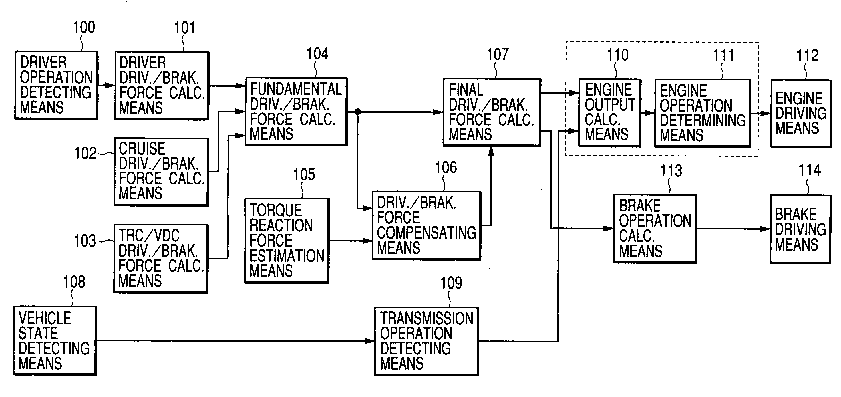
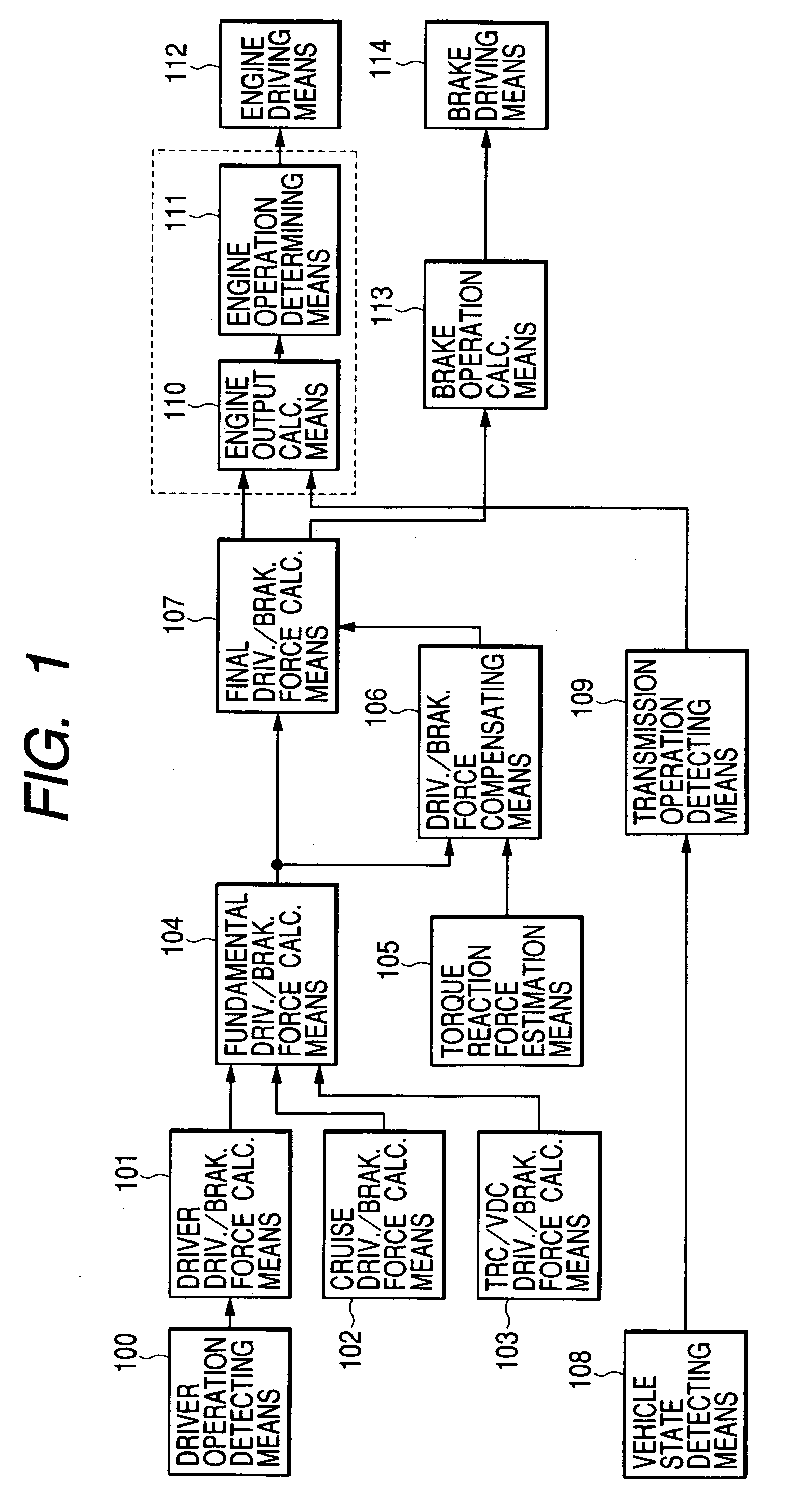
[0056]FIG. 1 is a block diagram of the vehicle vibration control apparatus of the present invention.

[0057] Driver operation detecting means 100 detects an operation quantity by a driver of an accelerator pedal, brake pedal and steering wheel, e.g., a setting down strokes of the accelerator pedal and brake pedal and turning angle of the steering, or alternatively a throttle state and brake master cylinder pressure.

[0058] Driver driving and braking force calculating means 101 calculates a driving force and braking force in accordance with the driver's intention on the basis of the operation quantity detected by the driver operation detecting means 100. Further, cruise driving and forces calculating means 102 calculates a driving force and braking force requested by a cruise control apparatus if any. Further, Traction (TRC) / vehicle demeanor control (VDC) driv. and brak. force calc. means 103 calculates a driving...


PUM


Abstract

An object of the present invention is to execute an optimum control of vibrations due to a driver's operation of an accelerator pedal, steering wheel and brake pedal. The operation instructions are inputted into a vibration calculating means (kinetic model) comprising a vehicle body model, suspension model and tire model. Conventional kinetic model controlled the suspension in order to suppress the vehicle body vibration. However, in the kinetic model of the present invention, the tire vibration due to a change in the engine output is first absorbed by the suspension, whereby a residual vibration which was not be absorbed yet by the suspension is transferred to the vehicle body. The operation inputs are compensated by the three feed-back loops between the outputs of the above-mentioned three portions and input of the tire portion, giving the highest priority on the vehicle body model.

Description

BACKGROUND OF THE INVENTION [0001] 1. Field of the Invention [0002] The present invention relates to a vibration control apparatus for an automotive vehicle and particularly to a vehicle control apparatus for suppressing vibrations such as a front / rear vibration, left / right vibration and up / down vibration, caused by a driver's operation of an accelerator, steering and brake. [0003] 2. Description of the Related Art [0004] One of the conventional vibration control is made through a suspension, wherein a squat and dive during driving and braking are suppressed by a suspension geometry, or wherein the vibrations are suppressed by changing a damper spring or stiffness characteristics of the suspension, as disclosed in JP2001-30728A, pages 2-8, 11 and 12, FIG. 6. [0005] Further, a driving force control method for suppressing the vibration of the vehicle body due to the driving force caused by the accelerator operation is disclosed in JP9-112329A, 1997, pages 2-4 and 6, FIG. 3. [0006] In ...

Claims


Application Information

Patent Timeline
IPC IPC(8): B60G17/016B60G17/015B60G17/0165B60G17/0195B60T8/00B60T8/173B60T13/66B60W10/04B60W10/06B60W10/18B60W10/188B60W10/20B60W30/00B60W30/20F16F15/02
CPCB60G17/016Y02T10/56B60G17/0195B60G2400/102B60G2400/206B60G2400/208B60G2400/30B60G2400/61B60G2400/63B60G2400/64B60G2800/162B60G2800/18B60G2800/22B60G2800/24B60G2800/916B60K2741/205B60T13/662B60T2270/86B60W10/06B60W10/18B60W30/20F16F15/02B60G17/0165B60W10/04B60W30/1819B60W2050/0031Y02T10/40
Inventor KATAOKA, MOTOAKIMATSUMOTO, TOSHIKITASHIRO, TSUTOMUMABUCHI, MAMORUSAWADA, MAMORU
Owner DENSO CORP
Why Eureka
Try Eureka