Processing apparatus

a processing apparatus and processing technology, applied in lighting and heating apparatus, muffle furnaces, furnaces, etc., can solve the problems of difficult to execute uniform processing on workpieces, tilt of stage 8/b>, and easy vibration during operation, so as to achieve a greater ease of maintenance work on the processing apparatus and a higher degree of efficiency

Inactive Publication Date: 2005-03-10
TOKYO ELECTRON LTD
View PDF15 Cites 38 Cited by
  • Summary
  • Abstract
  • Description
  • Claims
  • Application Information

AI Technical Summary

Benefits of technology

[0021] In the processing apparatus adopting the structure described above, the stage is fixed to the processing container at at least two positions and thus, the stage is held horizontally even when the processing container is in a vacuum state inside to enable uniform processing on the workpiece. In addition, maintenance work on the processing apparatus can be conducted with greater ease since the positional adjustment of the lifter pins and the like do not need to be performed frequently.
[0022] Moreover, since the stage supporting unit is fixed at at least two positions, the stage can be held in a horizontal state in a stable manner. In addition, as the stage supporting unit is fixed at the inner side surface of the flange pipe through which the processing container is exhausted, the processing container can be exhausted uniformly with a higher degree of efficiency.

Problems solved by technology

In addition, there is a problem in that a vibration tends to occur readily during operation.
There is another problem in that when a vacuum state is achieved inside the plasma processing apparatus 1, the vertical drive unit, which supports stage 8 and also causes a vertical movement of the stage 8, becomes tilted due to pressure of the external atmospheric pressure, thermal distortion of the stage 8 or the weight of the stage 8, resulting in a tilt of the stage 8.
This necessitates frequent horizontal adjustment of the stage 8 and frequent alignment of the lifter pins 14, which makes it difficult to execute uniform processing on workpieces.

Method used


Image

  • Processing apparatus
  • Processing apparatus
  • Processing apparatus

Examples


first embodiment

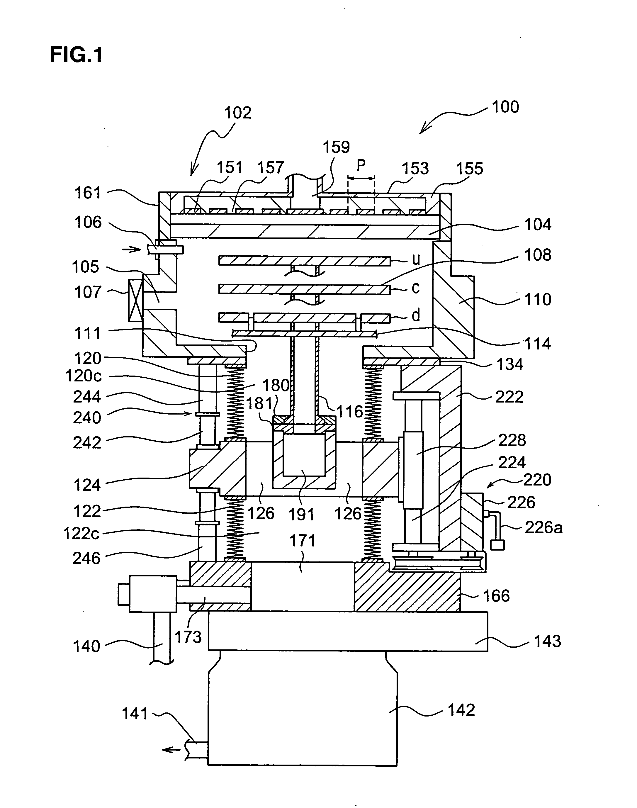
[0031] (First Embodiment)

[0032]FIG. 1 is a schematic sectional view of the structure adopted in a plasma processing apparatus 100 in the first embodiment of the present invention. As shown in FIG. 1, the plasma processing apparatus 100 includes a chamber 110. The chamber 110, which is a cylindrical processing container with an open upper portion, is constituted with a conductive material, e.g., a metal such as aluminum or stainless steel, or an alloy thereof.

[0033] At the open upper portion of the chamber 110, a flat dielectric plate 104 is horizontally disposed. The dielectric plate 104 may be constituted of quartz, a ceramic such as AlN or Al2O3, or sapphire and has a thickness of, for instance, approximately 20 to 30 mm. A seal member (not shown) which may be an O-ring is disposed between the chamber 110 and the dielectric plate 104 to maintain an airtight condition.

[0034] Above the dielectric plate 104, a radial antenna unit 102, which is a type of slot antenna, is installed. ...

second embodiment

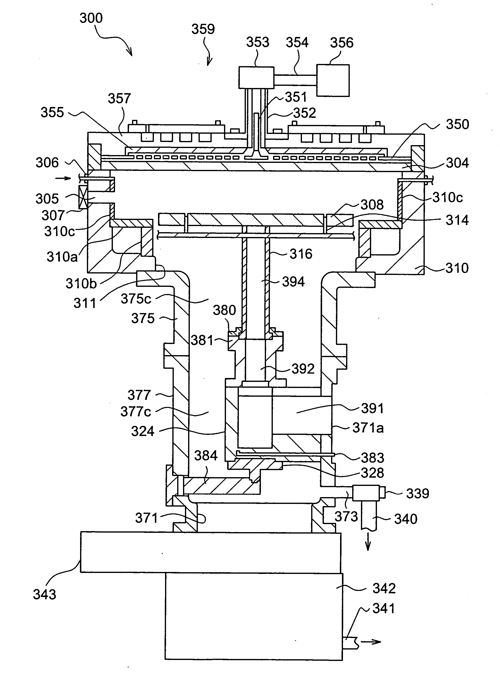
[0083] (Second Embodiment)

[0084]FIG. 5 is a schematic sectional view of the structure adopted in a plasma processing apparatus 300 in the second embodiment of the present invention. As shown in FIG. 5, the processing apparatus 300 includes a cylindrical chamber 310 with an open top. The chamber 310 is constituted with a conductive material, e.g., a metal such as aluminum or stainless steel, or an alloy thereof.

[0085] At the open top of the chamber 310, a flat dielectric plate 304 is horizontally disposed. The dielectric plate 304 may be constituted of quartz or ceramic and has a thickness of, for instance, approximately 20 to 30 mm. A seal member (not shown) which may be an O-ring is disposed between the chamber 310 and the dielectric plate 304 to maintain an airtight condition.

[0086] Above the dielectric plate 304, a radial antenna unit 359, which may be a type of slot antenna, is installed. The radial antenna unit 359 constituted with radial line slot antennas 350, 355 and 357 i...


PUM

PropertyMeasurementUnit
thicknessaaaaaaaaaa
frequencyaaaaaaaaaa
frequencyaaaaaaaaaa

Abstract

A plasma processing apparatus 100 used to execute a specific type of processing such as plasma processing on a workpiece by supplying a processing gas into a chamber 110 while applying high-frequency power to generate plasma includes a stage 108 on which the workpiece is placed and a stage supporting unit 124 that holds the stage 108. Bellows 120 and 122 are disposed above and below the stage supporting unit 124 to support the stage 108 in a horizontal state relative to the chamber 110. Thus, a plasma processing apparatus that does not allow the workpiece stage to become tilted, affords ease of maintenance and is capable of stable processing is provided. In addition, the internal spaces at the bellows 120 and 122 are used as an exhausting pipe to achieve efficient and uniform exhaustion of the chamber 110.

Description

CROSS-REFERENCE TO RELATED APPLICATIONS [0001] This application is a continuation-in-part of International Application PCT / JP03 / 00159, filed on Jan. 10, 2003, which was not published under PCT Article 21(2) in English. The contents of that International Application are incorporated herein by reference in its entirety.FIELD OF THE INVENTION [0002] The present invention relates to a processing apparatus that executes a specific type of processing on a workpiece, and more specifically, it relates to a processing apparatus having a stage on which the workpiece is placed. DESCRIPTION OF RELATED ART [0003] Processing apparatuses of this type include microwave plasma processing apparatuses that may be utilized in, for instance, semiconductor element production. A microwave plasma processing apparatus adopts a structure that allows the stage to move up / down freely, since an antenna (electrode) and the workpiece stage are set over different distances from each other at the time of plasma ign...

Claims


Application Information

Patent Timeline
Patent Type & Authority Applications(United States)
IPC IPC(8): H01L21/00H01L21/687
CPCH01J37/3244H01L21/68792H01L21/67069H01J37/32733
Inventor TANAKA, SUMI
Owner TOKYO ELECTRON LTD
Why Eureka
Try Eureka