Continuous prebaked anode carbon block

A prebaked anode and carbon block technology, which is applied in the field of continuous prebaked anode carbon blocks, can solve the problems of electric energy waste, environmental pollution, and time-consuming replacement of anodes, and achieve the effect of reducing heat conduction

Active Publication Date: 2019-07-23
贵州铝城铝业原材料研究发展有限公司
View PDF13 Cites 0 Cited by
  • Summary
  • Abstract
  • Description
  • Claims
  • Application Information

AI Technical Summary

Problems solved by technology

[0006] In summary, the prior art has the following technical defects: 1. The existing prebaked anode production of electrolytic aluminum causes huge loss of heat energy when replacing the anode, which takes time to replace the anode and causes waste of electric energy. The conditions are extremely bad, the waste of carbon materials is large, and the environment is seriously polluted; 2. Chinese patent 201710088066.4 discloses the method and structure of the prebaked anode aluminum electrolysis online connection anode. When the old carbon block is to be connected with the new carbon block, the temperature reaches 750 ° C The temperature difference between the new carbon block and the normal temperature is above 700°C. After the two are bonded, as the temperature of the new carbon block gradually rises to about 750°C, due to thermal expansion and contraction, the volume of the new carbon block will expand and bond. Shear occurs at the place and the bond is not strong

Method used


Image

  • Continuous prebaked anode carbon block
  • Continuous prebaked anode carbon block
  • Continuous prebaked anode carbon block

Examples


Embodiment Construction

[0051] The present invention will be further described below in conjunction with the accompanying drawings and embodiments, but not as a basis for limiting the present invention.

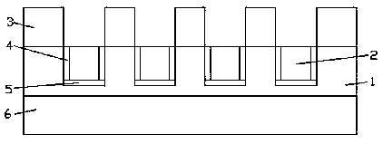
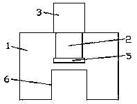
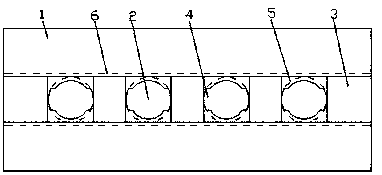
[0052] Example. A continuous prebaked anode carbon block consisting of Figure 1-9 As shown, it includes a carbon block body 1, a group of carbon bowls 2 are arranged on the long axis center line on the top of the carbon block body 1, a steel claw connecting ring groove 5 is provided at the bottom of the carbon bowl 2, and the long axis of the top of the carbon block body 1 above the carbon bowl 2 A connection protrusion 3 is provided on the center line, and a through connection groove 6 is provided at the bottom of the carbon block body 1 below the connection protrusion 3 .

[0053] The wall of the charcoal bowl 2 is provided with a mechanical steel claw channel vertical groove 4.

[0054] The thickness of the carbon block body 1 is 400-500 mm.

[0055] The carbon bowl 2 of the old carbon block ...


PUM

PropertyMeasurementUnit
thicknessaaaaaaaaaa
heightaaaaaaaaaa

Abstract

The invention discloses a continuous prebaked anode carbon block. A carbon block body is included. The middle line of the long axis of the upper portion of the carbon block body is provided with a setof carbon bowls. The bottoms of the carbon bowls are provided with casting-mechanical composite steel claw connecting ring grooves. The middle lines of the long axes of the tops of the parts, on thetwo sides of the carbon bowls, of the carbon block body are provided with connecting convex heads. The bottoms of the parts, below the connecting convex heads, of the carbon block body are provided with penetration connecting grooves. The continuous prebaked anode carbon block has the beneficial effects that the continuous prebaked anode carbon block is matched with a casting-mechanical compositesteel claw, continuous usage of a prebaked anode can be achieved, the anode carbon block connecting time is short, usage is convenient, electrolysis energy consumption is reduced, anode scraps are eliminated, the labor intensity is lowered, and new and old carbon block bonding is firm. After an old carbon block is connected with the convex heads and cooled, the old carbon block is connected with anew carbon block, new and old carbon block bonding and connecting reliability and firmness are ensured, and bonding layer shearing is prevented; and through the structures and the usage manners of the connecting convex heads, the carbon bowls and filling blocks, usage of the casting-mechanical composite steel claw is effectively matched, and an existing electrolytic cell can be directly connectedwith the anode carbon block.

Description

technical field [0001] The invention relates to a prebaked anode carbon block for an aluminum electrolytic cell, in particular to a continuous prebaked anode carbon block. Background technique [0002] Modern electrolytic aluminum processes use prebaked anodes to produce electrolytic aluminum. When the electrolytic cell is working, the anode assembly is composed of aluminum guide rod, explosion disc, anode steel claw, phosphorus pig iron casting layer and prebaked anode carbon block. The prebaked anode carbon block is generally a cuboid with a stable geometric shape. It uses stone tar and pitch coke as the aggregate and coal tar pitch as the binder. It has different sizes according to the size of the electrolytic cell current and the process. The current density is generally in the range of 0.68-0.9A / cm2, and the service life of each carbon block is generally about 30 days. [0003] In the production process of electrolytic aluminum, the carbon anode and the oxygen decompo...

Claims


Application Information

Patent Timeline
Patent Type & Authority Applications(China)
IPC IPC(8): C25C3/12
CPCC25C3/125
Inventor 邹铜华邹建明
Owner 贵州铝城铝业原材料研究发展有限公司
Why Eureka
Try Eureka