Fluid delivery tube structural body

a technology of pipe structure and discharge pipe, which is applied in the direction of shaping cutters, manufacturing tools, mechanical equipment, etc., can solve the problems of reducing the cost and prolonging the service life of the cutter used in the machining

Inactive Publication Date: 2005-03-10
BIC IND
View PDF10 Cites 11 Cited by
  • Summary
  • Abstract
  • Description
  • Claims
  • Application Information

AI Technical Summary

Benefits of technology

[0005] The present invention is developed in the light of the above points. An object of the present invention is to provide a fluid discharge pipe structure which can feed a coolant and a cutting and grinding lubricant of high cooling effect to a work which is machined by various kinds of machine tools and a cutter thereof, considerably improve the service life of the cutter, and feed the liquid lubricant to a desired member of various kinds of devices and appliances.

Problems solved by technology

In addition, by feeding the coolant to the cutter of the machine tool and the work via this fluid discharge pipe structure, the coolant is clung more around the cutter and the work to effectively cool them, prolongs the service life of the cutter used in the machining, and reduces the cost considerably.

Method used


Image

  • Fluid delivery tube structural body
  • Fluid delivery tube structural body
  • Fluid delivery tube structural body

Examples


Embodiment Construction

[0029] Embodiments of the present invention will be described below.

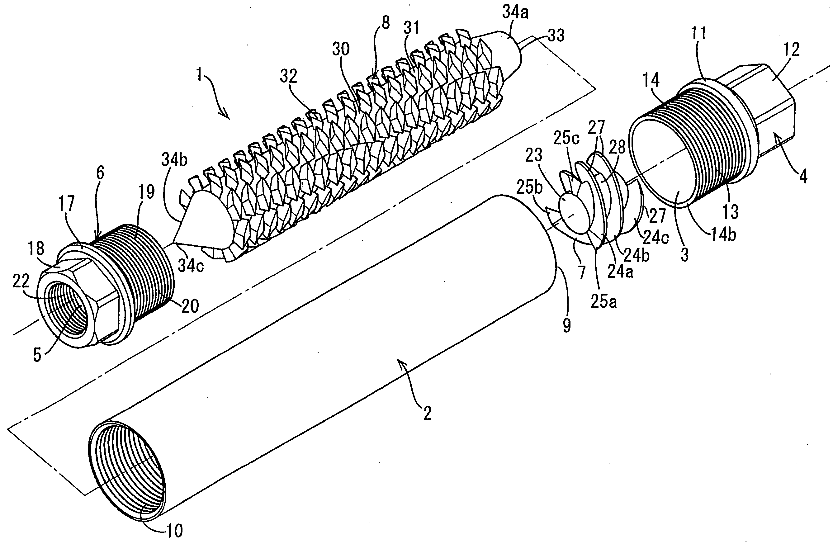
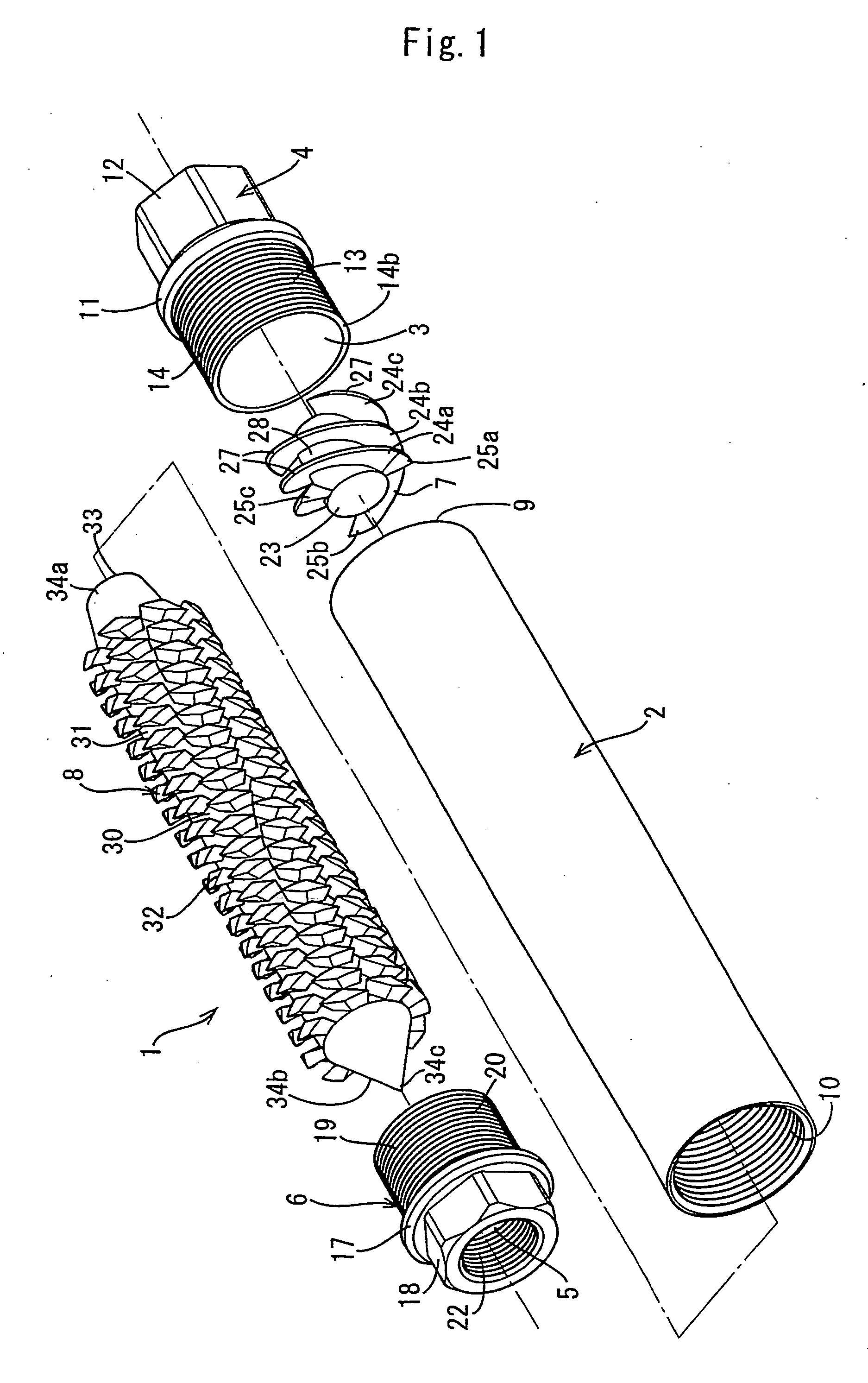
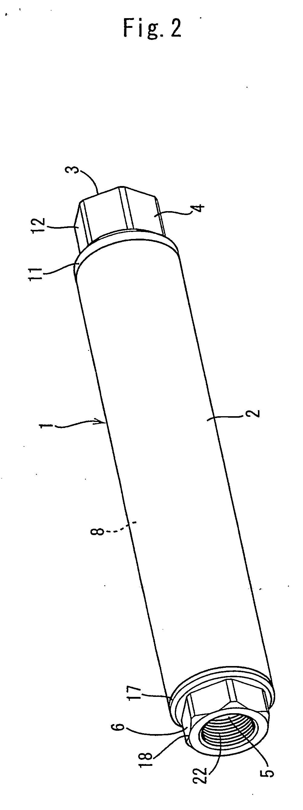
[0030] FIGS. 1 to 7 show a fluid discharge pipe structure 1 in accordance with the present invention. FIG. 1 is an assembly view of the fluid discharge pipe structure of the present invention, FIG. 2 is a perspective view of the fluid discharge pipe structure of the present invention, FIG. 3 is a longitudinal sectional view of the fluid discharge pipe structure of the present invention, FIG. 4 is a schematic representation of a large number of regularly disposed diamond-shaped projecting parts of a flip-flop phenomenon generating shaft body of the present invention, FIG. 5 is a schematic representation of one diamond-shaped projecting part of the flip-flop phenomenon generating shaft body of the present invention, FIG. 6 is a schematic representation of a spiral blade formed on a spiral blade body of the present invention, and FIG. 7 is a schematic representation of an application of the fluid discharge pipe struct...


PUM

PropertyMeasurementUnit
angleaaaaaaaaaa
angleaaaaaaaaaa
widthaaaaaaaaaa

Abstract

A fluid discharge pipe structure comprises a cylindrical body 2, an inlet side connection member 4 having a through hole 3 formed in one end part of the cylindrical body 2, an outlet side connection member 6 having a through hole 5 formed in the other end part of the cylindrical body 2, a spiral blade body 7 having spiral blades 24a, 24b and 24c on an outer circumference thereof and built in close to the inlet side connection member 4 of the cylindrical body 2, and a flip-flop phenomenon generating shaft body 8 built in close to the outlet side connection member 6 of the cylindrical body 2.

Description

TECHNICAL FIELD [0001] The present invention relates to a fluid discharge pipe structure which is used for feeding a coolant (cooling water) or a cutting and grinding lubricant to a contact part of a work with a cutter of various kinds of machine tools including a cutting machine and a grinding machine, and feeding a lubricating oil to a crank of an engine, a crank of a press, a wire drawing die or the like. BACKGROUND ART [0002] In general, when a metal or the like is machined into a desired shape, a work fixed to a predetermined position is formed into the desired shape by a machine tool such as a lathe, a drilling machine, and a milling machine while applying a cutter such as a cutting tool and a drill to the work. [0003] During this machining operation, a coolant stored in a tank provided on the machine tool or the like is fed to the cutter and the work by a pump via a pipe and a nozzle so that degradation of hardness of a blade tip, distortion of the work, deposition of the wor...

Claims


Application Information

Patent Timeline
Patent Type & Authority Applications(United States)
IPC IPC(8): B05B1/34B23Q11/00B23Q11/10
CPCB05B1/3447Y10T407/14B23Q11/10B23Q11/1084
Inventor NEGORO, KATSUJI
Owner BIC IND
Why Eureka
Try Eureka