Circuit and method for driving pixel of organic electroluminescent display

a technology of electroluminescent display and circuit, which is applied in the direction of electroluminescent light sources, static indicating devices, instruments, etc., can solve the problems of non-uniform brightness, differences in driving voltage of connected pixels, and complex wiring of el panels, so as to simplify the number of wirings and wiring processes

Inactive Publication Date: 2005-03-10
SAMSUNG DISPLAY CO LTD
View PDF5 Cites 65 Cited by
  • Summary
  • Abstract
  • Description
  • Claims
  • Application Information

AI Technical Summary

Benefits of technology

[0025] The present invention provides a circuit and method for driving pixels in an organic electroluminescent display capable of simplifying the number of wirings and wiring processes by implementing a compensation circuit using a previous scan line and a scan line without adding an additional signal line.

Problems solved by technology

This leads to differences between the driving voltages of the connected pixels.
Further, even if the voltages are the same, the difference of the threshold voltage Vth in the thin film transistor is generated due to the non-uniformity of the manufacturing process, resulting in a variance to the amount of current supplied to the organic EL device OLED, such that brightness becomes non-uniform.
However, in the conventional pixel driving circuit of FIG. 3, an additional threshold voltage compensation control line AZ and light emitting control line AZB are added in addition to the data line and the scan line, so that the wiring of the EL panel becomes more complex, and thus, the number of manufacturing processes increases, leading to an increase in the manufacture cost.

Method used


Image

  • Circuit and method for driving pixel of organic electroluminescent display
  • Circuit and method for driving pixel of organic electroluminescent display
  • Circuit and method for driving pixel of organic electroluminescent display

Examples


Embodiment Construction

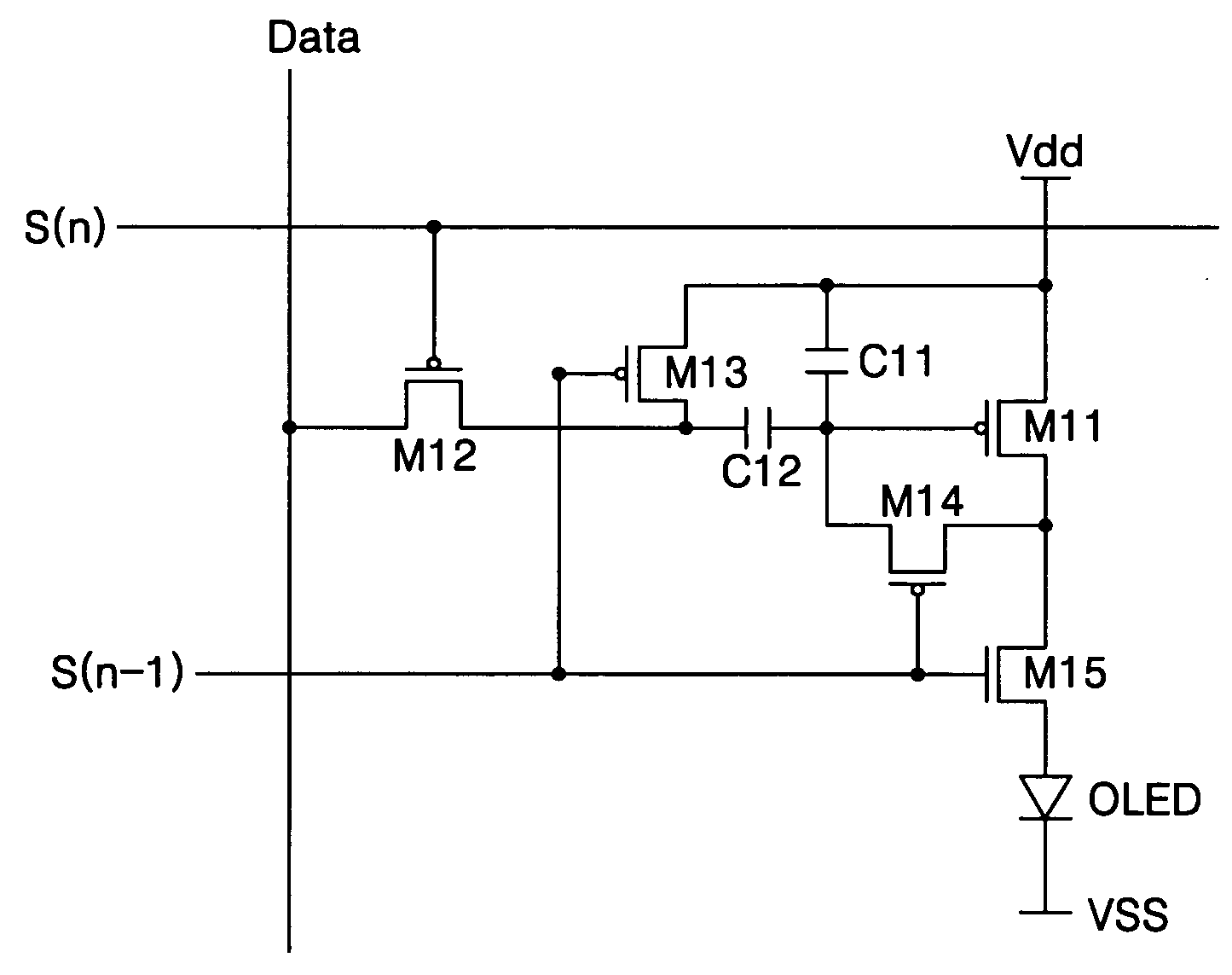
[0048]FIG. 5 is a circuit diagram of a pixel driving circuit of an organic electroluminescent display in an exemplary embodiment according to the present invention. The pixel driving circuit may also be referred to as a pixel circuit.

[0049] In FIG. 5, OLED indicates an organic EL device, M11˜M15 indicate first to fifth transistors, C11 indicates a first capacitor, and C12 indicates a second capacitor.

[0050] The organic EL device OLED emits light that corresponds to the amount of applied current. For the first thin film transistor M11, a source is connected to the power supply voltage Vdd and a drain is connected to a source of the fifth thin film transistor M15. The first thin film transistor M11 supplies the organic EL device OLED with a current that corresponds to the data voltage applied to its gate through the second thin film transistor M12.

[0051] For the third thin film transistor M13, a source is connected to the power supply voltage Vdd, a gate is connected to an (n−1)th ...


PUM


Abstract

A circuit and method for driving pixels in an organic electroluminescent display that reduces the number of wirings of a compensation circuit for addressing brightness non-uniformity. The pixel driving circuit includes an organic electroluminescent device that emits light corresponding to an amount of a current being applied. A first transistor is connected to a power supply voltage and applies the current corresponding to a data voltage to the organic electroluminescent device. A first capacitor stores the data voltage, and a threshold voltage compensation unit stores a threshold voltage of the first transistor. A second transistor transmits the data voltage from a data line in response to a selection signal from an nth scan line. A switching unit electrically disconnects a second primary electrode of the first transistor from the organic electroluminescent device while the threshold voltage is stored in the threshold voltage compensation unit in response to a control signal.

Description

CROSS-REFERENCE TO RELATED APPLICATION [0001] This application claims priority to and the benefit of Korean Patent Application No. 2003-62851, filed Sep. 8, 2003, the disclosure of which is incorporated herein by reference in its entirety. BACKGROUND OF THE INVENTION [0002] 1. Field of the Invention [0003] The present invention relates to an organic electroluminescent (EL) display and, more particularly, to a circuit and method for driving pixels in an organic electroluminescent display that reduces the number of wirings of a compensation circuit for solving the brightness non-uniformity resulting from a threshold voltage difference of driving transistors arranged in an EL panel, thereby simplifying both the wirings of the EL panel and the driving method. [0004] 2. Description of the Related Art [0005] An organic EL device is an emissive device that emits a fluorescent material by recombining an electron and a hole, with which an EL display can have a fast response time and a low dr...

Claims


Application Information

Patent Timeline
Patent Type & Authority Applications(United States)
IPC IPC(8): G09G3/32H05B44/00G09G3/30
CPCG09G3/3233G09G2300/0819G09G2300/0852G09G2320/043G09G2310/0251G09G2320/0233G09G2300/0861G09G3/30
Inventor KIM, KEUM-NAM
Owner SAMSUNG DISPLAY CO LTD
Why Eureka
Try Eureka