Systems and methods for tracking moving targets and monitoring object positions

a technology of moving targets and positioning objects, applied in image analysis, instruments, computing, etc., can solve the problems of inability to distinguish target tissue, inability to be practical or feasible, and inability to distinguish markers, etc., and achieve the effect of enhancing the feature of input images

Inactive Publication Date: 2005-03-10
VARIAN MEDICAL SYSTEMS
View PDF102 Cites 104 Cited by
  • Summary
  • Abstract
  • Description
  • Claims
  • Application Information

AI Technical Summary

Benefits of technology

[0008] In accordance with an embodiment of the invention, a method for determining a position of an object is provided. The method includes acquiring an input image of the object, enhancing a feature in the input image, registering the input image with a template, and determining a position of the object based on the registering. The feature in the input image may be enhanced by determining a composite image of previously acquired input images, and subtracting the composite image from the input image. For example, the composite image may be determined by performing image averaging on the previously acquired input images. In one embodiment, the template is selected from a plurality of templates. In this case, the template that best matches an image in the input image is selected to be registered with the input image. The method has applications in a wide range of medical procedures. By means of non-limiting example, the method may be used to dynamically target a tissue in a medical procedure. For example, the method may be used to dynamically target a target region in radiation therapy, in which a radiation treatment beam can be continuously positioned to follow the target region or gated to deliver radiation based on the position of the target region. One advantage of such method is that it does not require the use of markers to determine the position of the target region.

Problems solved by technology

However, often soft tissue targets such as a variety of tumors are not visible in x-ray fluoroscopic images.
This is due to structures in front or behind the target tissue which are also visible in the x-ray images thus increasing the clutter to the level that the target tissue cannot be distinguished.
However, implantation of markers is intrusive to the patient, and it may not be practical or feasible in all cases.

Method used


Image

  • Systems and methods for tracking moving targets and monitoring object positions
  • Systems and methods for tracking moving targets and monitoring object positions
  • Systems and methods for tracking moving targets and monitoring object positions

Examples


Embodiment Construction

[0024] Various embodiments of the present invention are described hereinafter with reference to the figures. It should be noted that the figures are not drawn to scale and that elements of similar structures or functions are represented by like reference numerals throughout the figures. It should also be noted that the figures are only intended to facilitate the description of specific embodiments of the invention. They are not intended as an exhaustive description of the invention or as a limitation on the scope of the invention. In addition, an illustrated embodiment needs not have all the aspects or advantages of the invention shown. An aspect or an advantage described in conjunction with a particular embodiment of the present invention is not necessarily limited to that embodiment and can be practiced in any other embodiments of the present invention even if not so illustrated.

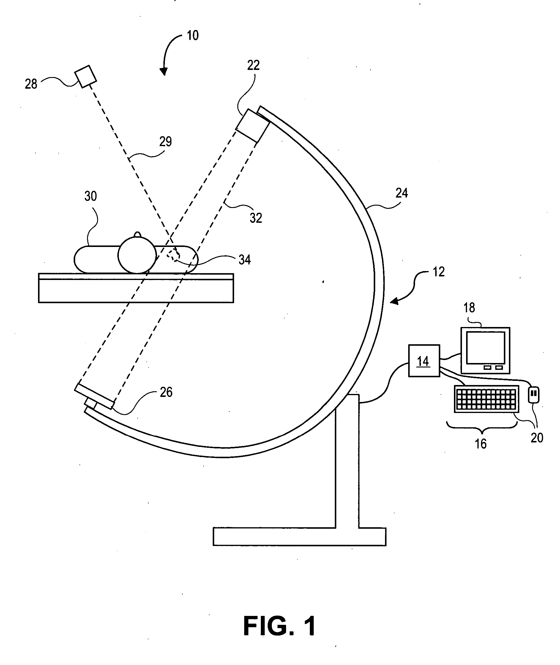
[0025]FIG. 1 illustrates a fluoroscopic system 10 with which embodiments of the present invention may ...


PUM


Abstract

A method of determining a position of a target region in a medical procedure includes acquiring an input image of a target region, enhancing a feature of the input image, registering the input image with a template, and determining a position of the target region in the input image based on the registering. A method of monitoring a position of an object includes providing a reference image of the object, acquiring a first image of the object, determining a first composite image based on the reference image and the first image, and determining whether the object has moved based at least on the first composite image.

Description

BACKGROUND OF THE INVENTION [0001] 1. Field of the Invention [0002] The field of the invention relates to methods and systems for determining and monitoring object positions, and more particularly, to systems and methods for tracking target regions and monitoring object positions in medical procedures. [0003] 2. Background of the Invention [0004] Radiation therapy involves medical procedures that selectively expose certain areas of a human body, such as cancerous tumors, to doses of radiation. The purpose of the radiation therapy is to irradiate the targeted biological tissue such that undesirable tissue is destroyed. Radiation has also been used to obtain image of tissue for diagnostic or treatment purposes. [0005] In a radiation treatment session, the position and movement of a target tissue can be monitored by an imaging system, such as a fluoroscopic imaging system, while radiation is delivered to the target tissue. This ensures that the target tissue is in a desired position wh...

Claims


Application Information

Patent Timeline
Patent Type & Authority Applications(United States)
IPC IPC(8): A61BG06K9/00G06K9/40G06T7/20
CPCG06T7/206G06T7/2053G06T7/254G06T7/262
Inventor MOSTAFAVI, HASSAN
Owner VARIAN MEDICAL SYSTEMS
Why Eureka
Try Eureka