Modular retaining wall

a technology of retaining walls and modules, applied in the direction of walls, piers, groynes, etc., can solve the problems of less than effective seawalls, requiring replacement and repairs, and erosion of land, and achieve the effects of reducing maintenance costs, improving strength, and speeding up installation

Inactive Publication Date: 2005-03-10
FORMTECH ENTERPRISES
View PDF27 Cites 44 Cited by
  • Summary
  • Abstract
  • Description
  • Claims
  • Application Information

AI Technical Summary

Benefits of technology

[0018] It is a further aspect of the invention to improve on existing seawall “sheet pilings” of plastic material by exposing a smooth face toward both the sea and the land using a substantially rigid three-dimensional structure which employs a double connection system which is locked into a fixed location. A connection hook is employed which allows for clearing of external material during installation. The final structure is hollow and can be filled with gravel, concrete, etc., to achieve a higher strength. The smooth surfaces are not only more visually appealing, but also make installation easier due to the ease of concrete form construction. Additionally, angled modules are provided which allow for a radiused appearance.
[0019] It is still a further object of this invention to employ a two point connection that makes for faster installation because the three-dimensional profile cannot twist or bow to the degree of existing two-dimensional products. This means less driving energy will be absorbed by the pile making it faster to drive. It also reduces rework required to correct misplaced piles in that they will not have to be withdrawn and replaced.

Problems solved by technology

Over the many years, there has long existed the problem of land erosion adjacent waterways, rivers, lakes and oceans wherein seawalls of various types have heretofore been constructed of wood, steel or cement.
The problem then as recognized by the inventor and thereafter, has been the enormous pressures and loads applied to the seawall which have ultimately destroyed the connection between adjacent seawall elements to render the seawall less than effective and ultimately requiring replacement and repairs.

Method used


Image

  • Modular retaining wall
  • Modular retaining wall
  • Modular retaining wall

Examples


Embodiment Construction

[0030] The invention is described with reference to the accompanying figures, which illustrate the best mode known to the inventor at the time of the filing of the application illustrating the modular retaining wall of the invention.

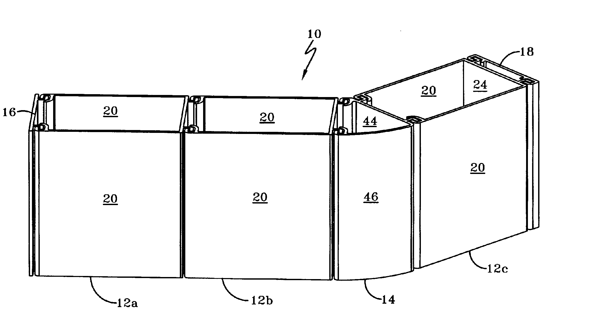
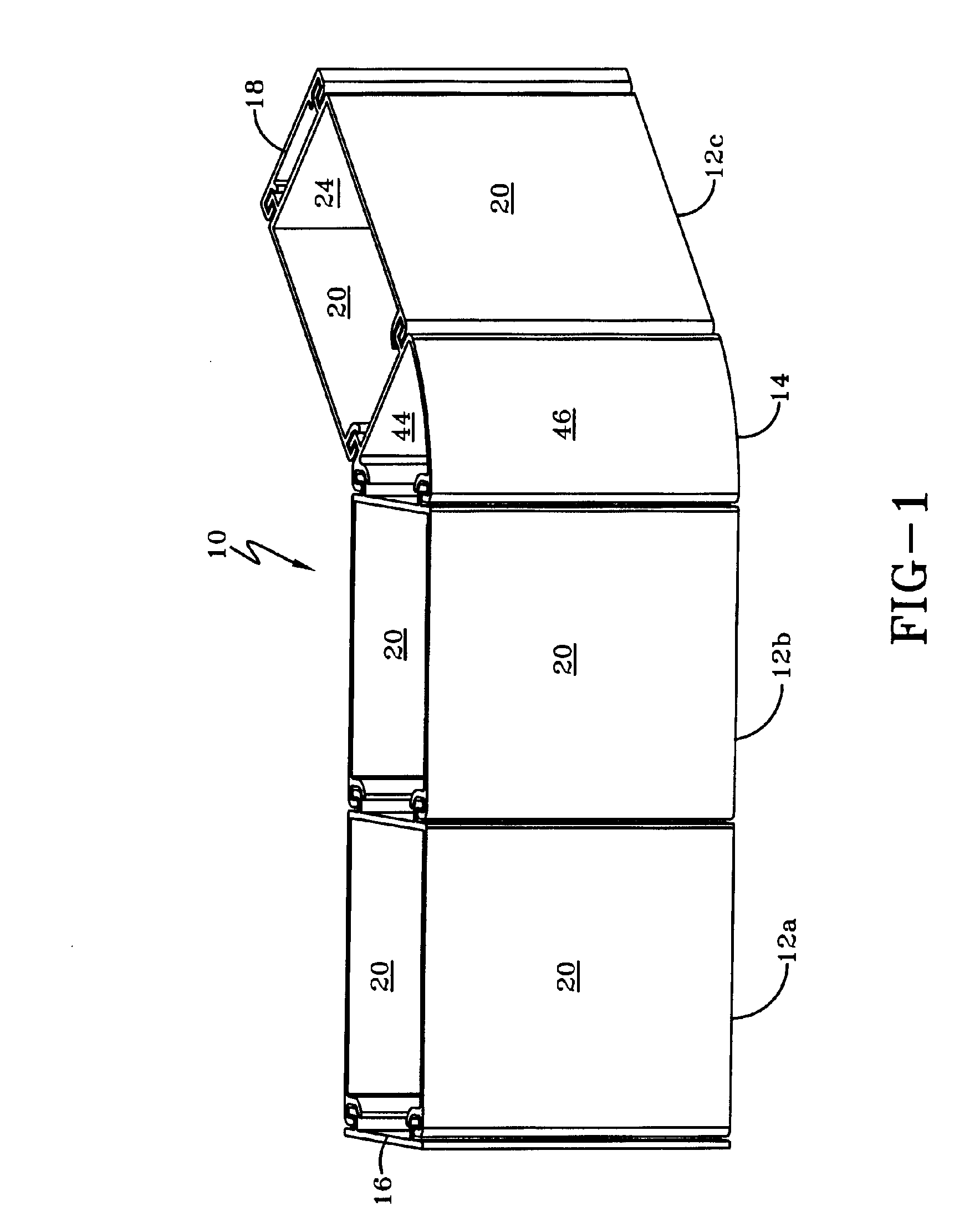
[0031] As better illustrated in FIG. 1, retaining wall 10 consists of various modules which form a contiguous barrier wall across a length of the modules when in their assembled state. Some modules are essentially interlocking linear U-shaped channels, e.g., 12a, 12b, and 12c whereas other interlocking modules, e.g., angled module 14, are used to impart non-linearity to the wall. As illustrated in the figure, the imparted angle is approximately 45°, although this is but an example of any angle between 1° and 180°, the end-use application, which in an aqueous environment will be the shoreline defining the requisite angularity required for the non-linear modules. The combination of linear U-shaped modules with non-linear modules provides essentially limit...


PUM


Abstract

A modular retaining wall with improved features is illustrated and described. Open or closed polygonal modules having channels disposed therein are set at least partially below a surface, said surface either being land-based or aqueous-based, and interfaces therebetween, e.g., shoreline, and attached to each other by respective fastening means which provide engaging connectivity between the modules.

Description

TECHNICAL FIELD [0001] This invention relates generally to retaining walls, and more specifically to retaining walls for use in controlling land erosion in contact with water. BACKGROUND OF THE INVENTION [0002] Over the many years, there has long existed the problem of land erosion adjacent waterways, rivers, lakes and oceans wherein seawalls of various types have heretofore been constructed of wood, steel or cement. Heretofore, efforts have been made to provide a series of seawall elements which are laterally aligned and in some manner interconnected and pounded down into the ground and anchored. Illustrative of earlier prior art efforts to provide a seawall, constructed of reinforced concrete, is U.S. Pat. No. 1,332,655 issued to R. B. Willard in 1920. The problem then as recognized by the inventor and thereafter, has been the enormous pressures and loads applied to the seawall which have ultimately destroyed the connection between adjacent seawall elements to render the seawall l...

Claims


Application Information

Patent Timeline
Patent Type & Authority Applications(United States)
IPC IPC(8): E02B3/06E02B3/14E02D5/03
CPCE02B3/06E02D5/03E02B3/14E04B2/8629E04B2002/867E04B2/84
Inventor DAVIDSAVER, JOHN E.YEANY, SCOTT A.
Owner FORMTECH ENTERPRISES
Why Eureka
Try Eureka