Cooling system for a turbine blade

Inactive Publication Date: 2005-03-10
SIEMENS ENERGY INC
View PDF20 Cites 15 Cited by
  • Summary
  • Abstract
  • Description
  • Claims
  • Application Information

AI Technical Summary

Benefits of technology

[0009] In at least one embodiment, the cooling system may include three first impingement ribs identified as an outer impingement rib, a middle impingement rib, and an inner impingement rib. A plurality of second and third impingement ribs may extend from the inner impingement rib and may intersect each other, thereby forming a plurality of triangular cavities. Orifices in the first impingement ribs provide axial impingement cooling to the first impingement ribs, and the orifices in the second and third impingement orifices may provide oblique impingement co

Problems solved by technology

In addition, turbine blades often contain cooling systems for prolonging the life of the blades and reducing the likelihood of failure as a result of excessive temperatures.
However, centrifugal forces and air flow at boundary layers often prevent some areas of the turbine blade from being adequately cooled, which results in the formation of localized hot spots.
Localiz

Method used


Image

  • Cooling system for a turbine blade
  • Cooling system for a turbine blade
  • Cooling system for a turbine blade

Examples


Example

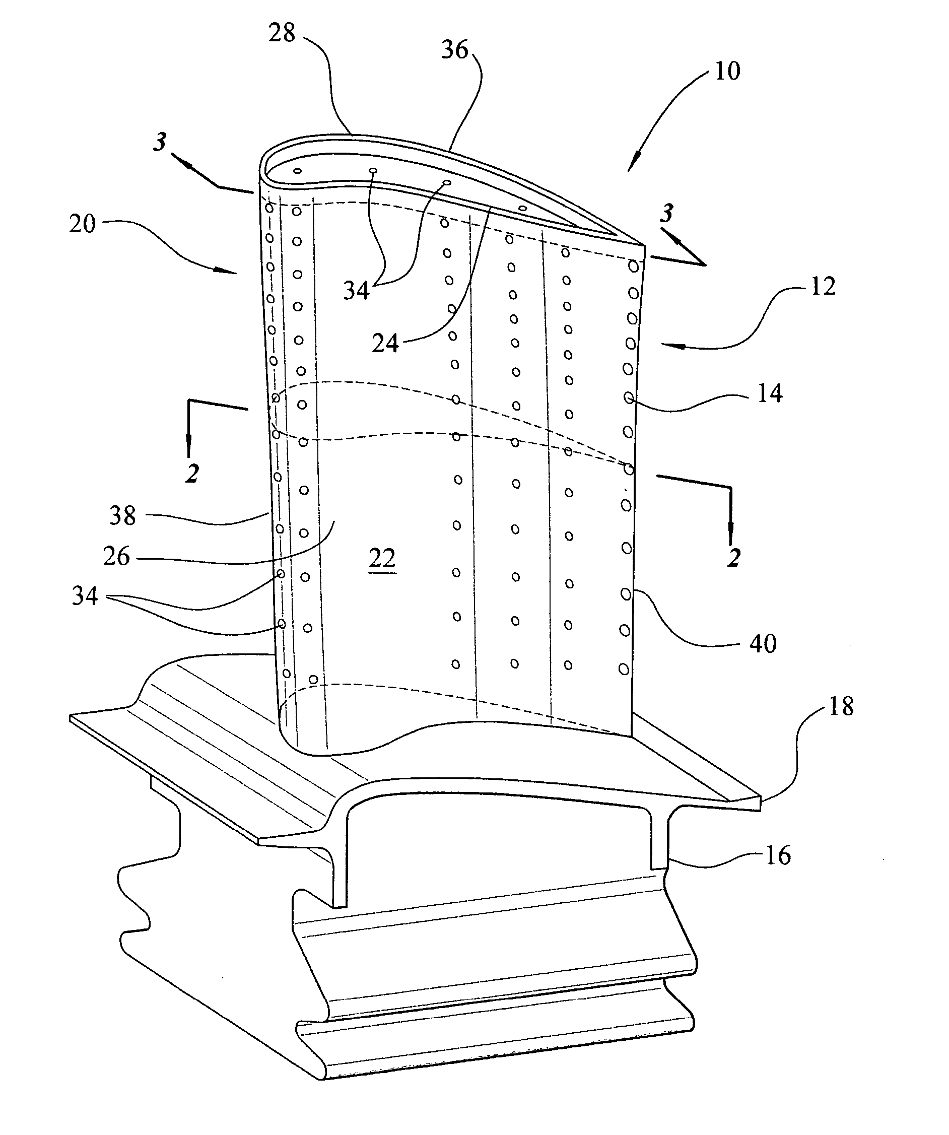
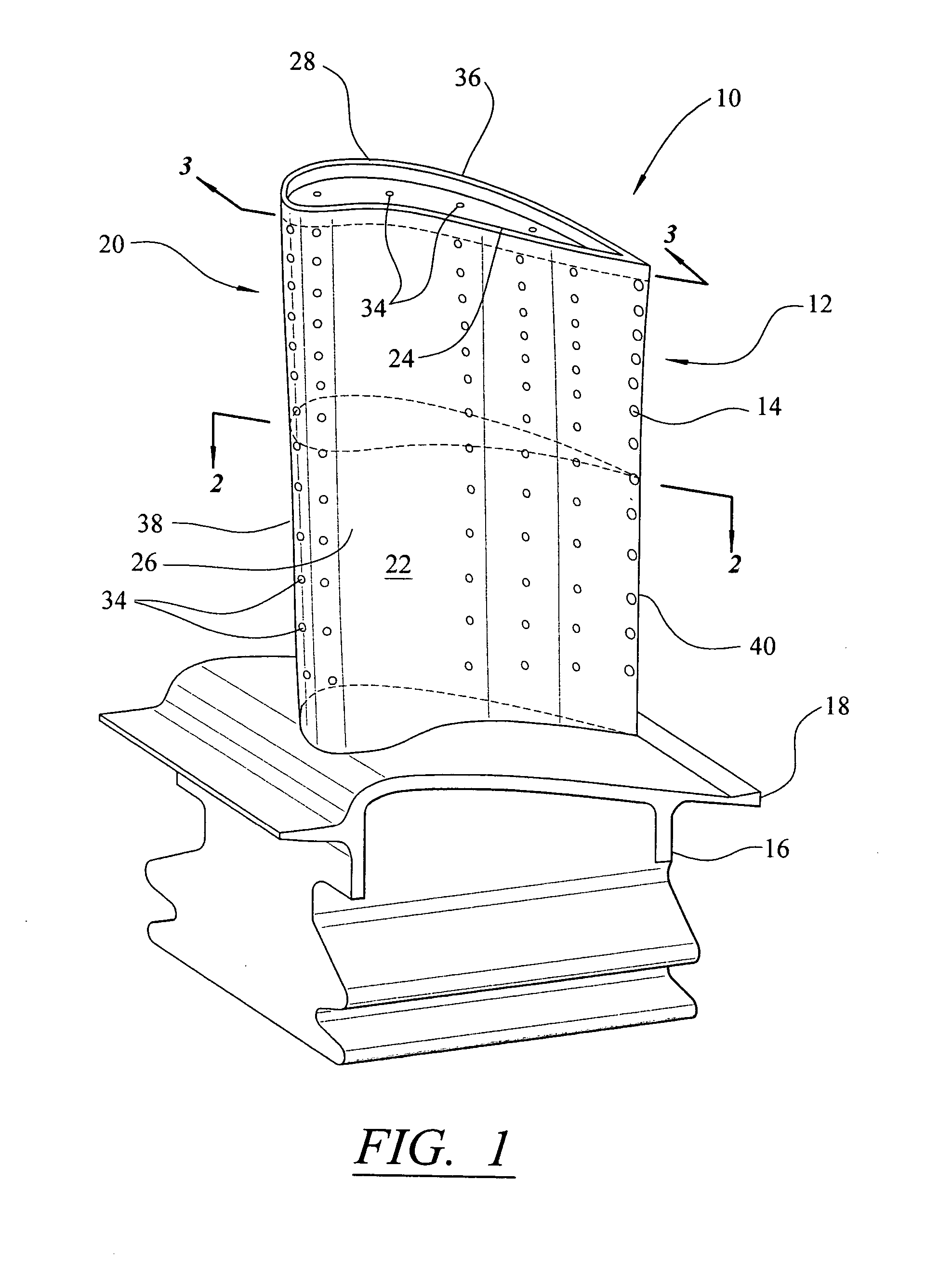
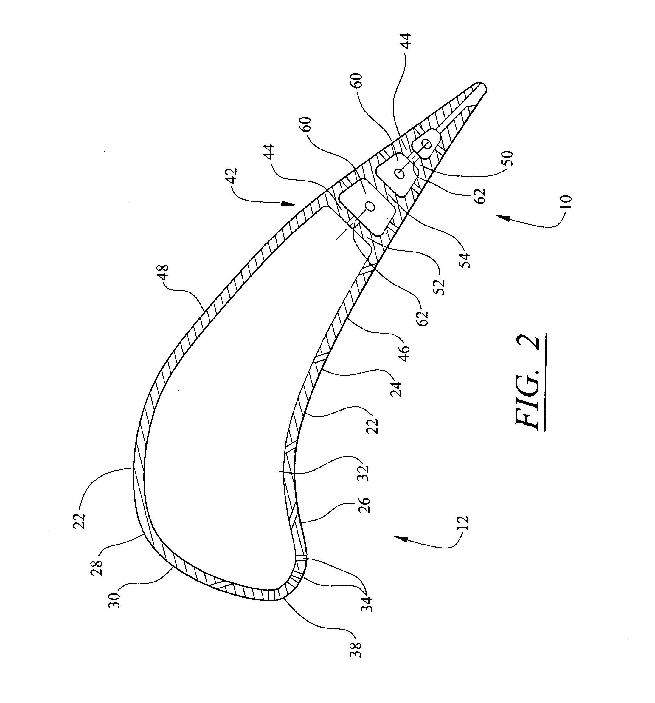
[0021] As shown in FIGS. 1-7, this invention is directed to a turbine blade cooling system 10 for turbine blades 12 used in turbine engines. In particular, turbine blade cooling system 10 is directed to a cooling system 10 located in a cavity 14, as shown in FIG. 2, positioned between two or more walls forming a housing 24 of the turbine blade 12. As shown in FIG. 1, the turbine blade 12 may be formed from a root 16 having a platform 18 and a generally elongated blade 20 coupled to the root 16 at the platform 18. Blade 20 may have an outer wall 22 adapted for use, for example, in a first stage of an axial flow turbine engine. Outer wall 22 may be formed from a housing 24 having a generally concave shaped portion forming pressure side 26 and may have a generally convex shaped portion forming suction side 28.

[0022] The cavity 14, as shown in FIG. 2, may be positioned in inner aspects of the blade 20 for directing one or more gases, which may include air received from a compressor (no...


PUM


Abstract

A turbine blade for a turbine engine having an impingement cooling system in at least the trailing edge of the turbine blade. The cooling system may include one or more first impingement ribs positioned generally parallel to the trailing edge and impingement ribs positioned obliquely relative to the first impingement ribs forming one or more triangular cavities. The impingement ribs may include orifices for allowing cooling gases to flow through the triangular cavities and be exhausted through the trailing edge of the turbine blade. The orifices in the second and third impingement ribs may be positioned obliquely relative to the an outer wall.

Description

FIELD OF THE INVENTION [0001] This invention is directed generally to turbine blades, and more particularly to hollow turbine blades having an intricate maze of cooling channels for passing gases, such as air, to cool the blades. BACKGROUND [0002] Typically, gas turbine engines include a compressor for compressing air, a combustor for mixing the compressed air with fuel and igniting the mixture, and a turbine blade assembly for producing power. Combustors often operate at high temperatures that may exceed 2,500 degrees Fahrenheit. Typical turbine combustor configurations expose turbine blade assemblies to these high temperatures. As a result, turbine blades must be made of materials capable of withstanding such high temperatures. In addition, turbine blades often contain cooling systems for prolonging the life of the blades and reducing the likelihood of failure as a result of excessive temperatures. [0003] Typically, turbine blades are formed from a root portion at one end and an e...

Claims


Application Information

Patent Timeline
IPC IPC(8): F01D5/14F01D5/18
CPCF01D5/14F05D2260/2212F05D2260/201F01D5/188
Inventor LIANG, GEORGE
Owner SIEMENS ENERGY INC
Why Eureka
Try Eureka