Orthopaedic implant and screw assembly

a technology for orthopaedic implants and screws, which is applied in the field of intramedullary nail or plate and screw assembly, can solve the problems of femoral head compression, screw sliding through the nail, excessive compression of the femoral head, etc., and achieves the effect of reducing mass in the cross section, increasing strength and resistance to tension

Inactive Publication Date: 2005-03-10
SMITH & NEPHEW INC
View PDF37 Cites 157 Cited by
  • Summary
  • Abstract
  • Description
  • Claims
  • Application Information

AI Technical Summary

Benefits of technology

[0009] Methods, devices and systems according to certain aspects of this invention allow treatment of bone fractures using one or both of an structure configured to be implanted in or stabilize a first bone fragment and a fastening assembly. The structure may take the form of a plate or other device for at least partial application to the outer surface of bone, or an implant for at least partial implantation within bone. Such implants may include a proximal section having a transverse aperture, and an aperture substantially along their length. Preferably, they include at least one cross-section in their proximal portions which features a shape that imparts additional strength and resistance to tension. Such shapes can be provided, for instance, by one or both (i) adding additional mass in lateral portions of the cross section, and (2) strategically adding and reducing mass in the cross section to take advantage of flange effects similar to the way flanges add structural benefits to I-beams and channels. One way to characterize such cross-sections, which can but need not be asymmetrical with respect to at least one axis, is that they generally feature a moment of inertia extending in a lateral direction from a point that is the midpoint of a line from a lateral tangent to a medial tangent of the cross section. In some structures, that line is coplanar with the axis of the transverse aperture and coplanar ...

Problems solved by technology

When an additional screw or pin is used, however, unequal forces applied to the separated screws or pins can cause the separate screws or pins to be pressed against the sides of the holes through which the separate screws or pins are intended to slide.
This may result in binding, which reduces the sliding of the screws or pins through the nail.
Conversely, a problem can result from excessive compression of the femoral head toward or into the fracture site.
In extreme cases, excessive sliding compression may cause the femoral head to be compressed all the way into the trochant...

Method used


Image

  • Orthopaedic implant and screw assembly
  • Orthopaedic implant and screw assembly
  • Orthopaedic implant and screw assembly

Examples


Embodiment Construction

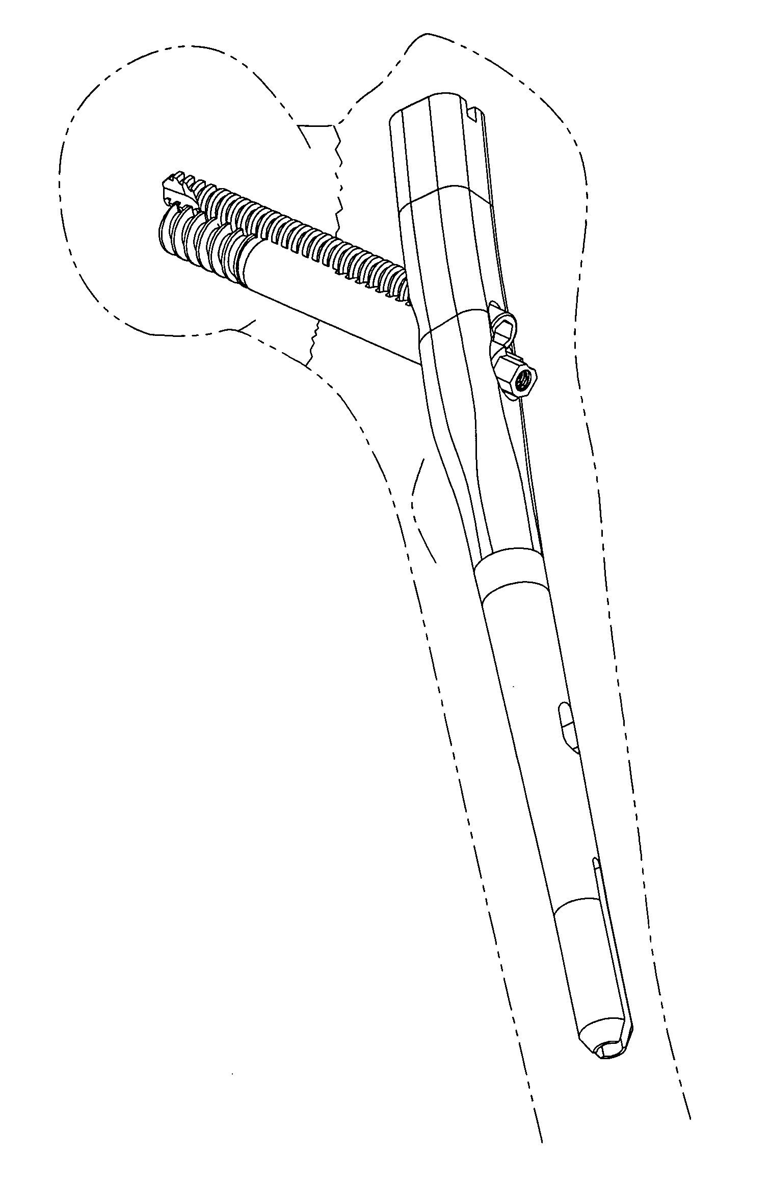
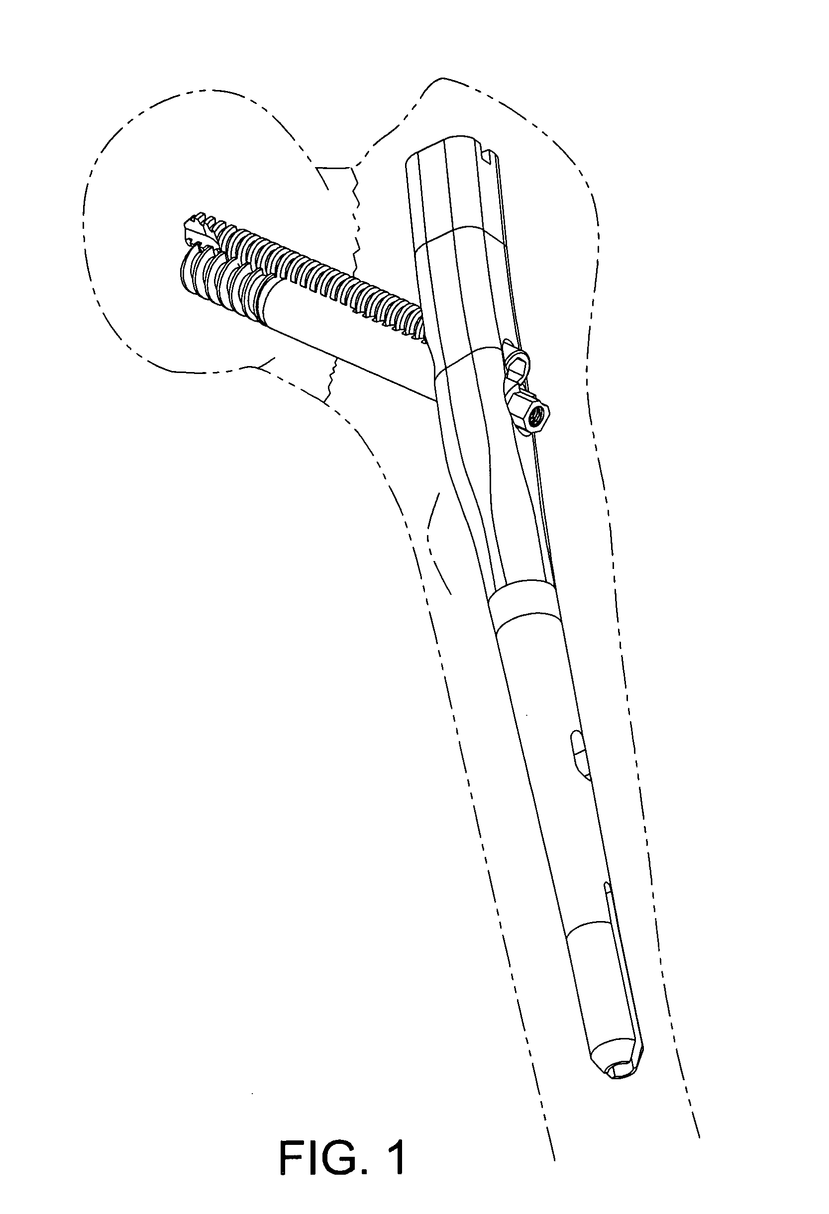
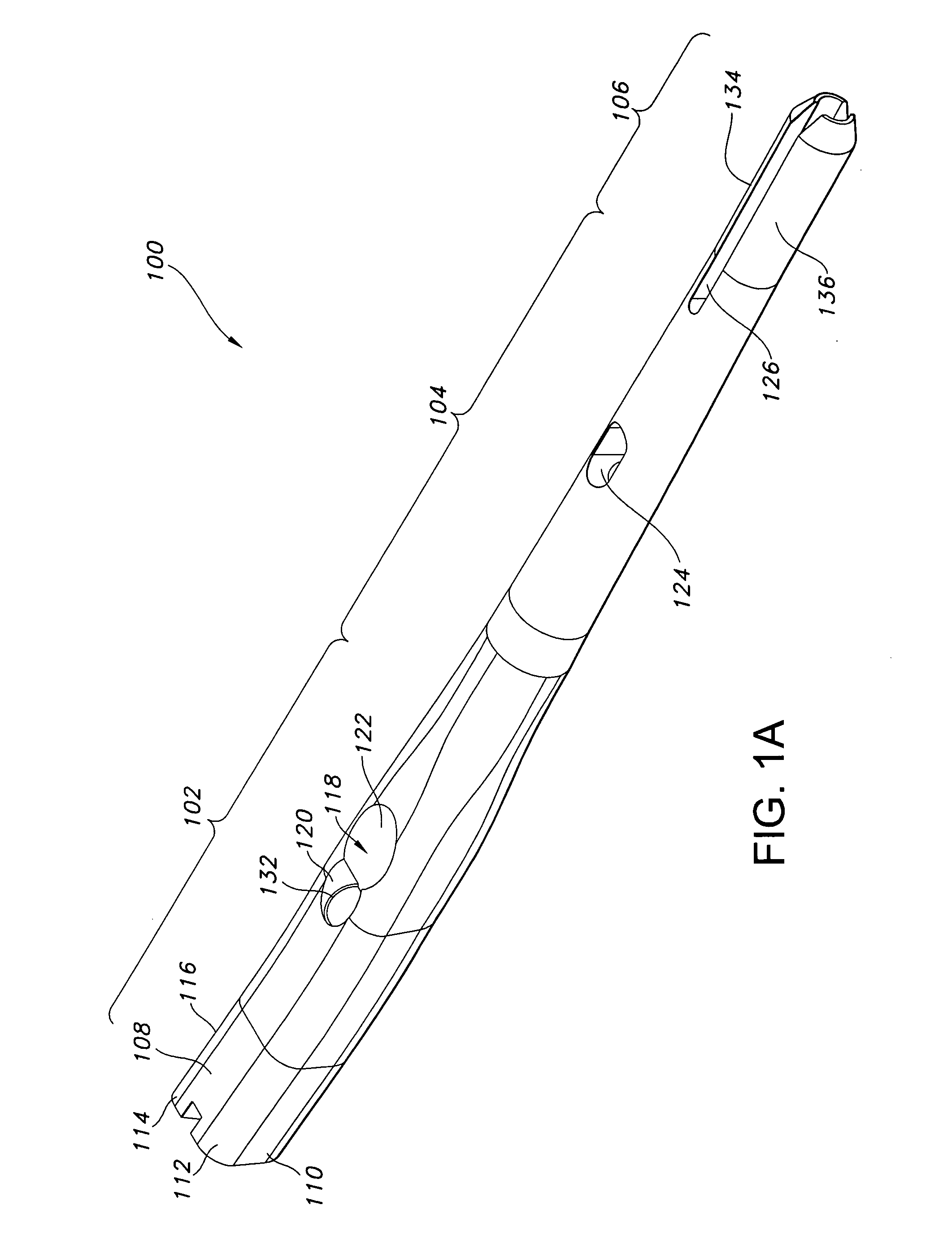
[0058] Methods, devices and systems according to embodiments of this invention seek to provide improved treatment of femur fractures. FIGS. 1-6 illustrate various views of one embodiment of an intramedullary nail 100 of the present invention. The intramedullary nail 100 has a longitudinal bore 130 throughout to aid in insertion in the bone. The intramedullary nail 100 has a proximal section 102, a transition section 104 and a distal section 106.

[0059] The proximal section 102 of the particular structure shown in FIGS. 1-6 preferably features an anatomically inspired shape that corresponds more accurately to typical cortical bone. One version of such shape is shown in the cross-sectional view of the proximal section 102 in FIG. 6. The particular cross-section of the proximal section 102 shown in FIG. 6 is generally non-circular along at least some portions of its length, and has a lateral side or aspect 108 that is larger than a medial side or aspect 109. The lateral side 108 and me...


PUM


Abstract

Systems, devices and methods are disclosed for treating fractures. The systems, devices and methods may include one or both of an implant, such as an intramedullary nail, and a fastening assembly, such as a lag screw and compression screw assembly. The implant in some embodiments has a proximal section with a transverse aperture and a cross-section that may be shaped to more accurately conform to the anatomical shape of cortical bone and to provide additional strength and robustness in its lateral portions, preferably without requiring significant additional material. The fastening assembly may be received to slide, in a controlled way, in the transverse aperture of the implant. In some embodiments, the engaging member and the compression device are configured so that the compression device interacts with a portion of the implant and a portion of the engaging member to enable controlled movement between the first and second bone fragments. This configuration is useful for, among other things, compressing a fracture.

Description

FIELD OF THE INVENTION [0001] The present invention generally relates to a system for coupling bone portions across a fracture and, more specifically, to an intramedullary nail or plate and screw assembly used to treat fractures of long bones such as the femur, humerus and tibia, and various periarticular fractures of these and other bones. BACKGROUND OF THE INVENTION [0002] There are a variety of devices used to treat fractures of the femur, humerus, tibia, and other long bones. For example, fractures of the femoral neck, head, and intertrochanteric region have been successfully treated with a variety of compression screw assemblies, which include generally a compression plate having a barrel member, a lag screw and a compressing screw. Examples include the AMBI® and CLASSIC™ compression hip screw systems offered by Smith & Nephew, Inc. In such systems, the compression plate is secured to the exterior of the femur, and the barrel member is inserted in a predrilled hole in the direc...

Claims


Application Information

Patent Timeline
IPC IPC(8): A61B17/16A61B17/72A61B17/74A61B17/78A61B17/80
CPCA61B17/1604A61B17/8061A61B17/1633A61B17/164A61B17/1668A61B17/1684A61B17/1728A61B17/72A61B17/7233A61B17/725A61B17/7258A61B17/7283A61B17/744A61B17/746A61B17/1615
Inventor JAMES, ANTHONY H.FERRANTE, JOSEPHMINES, ANGIE
Owner SMITH & NEPHEW INC
Why Eureka
Try Eureka