Memory wear leveling

a technology of memory wear and leveling, applied in the field of memory wear leveling, can solve the problems of affecting the use of memory architecture, and deteriorating of conventional memories (e.g. flash memories), and achieve the effect of reducing the wear of hotspots

Inactive Publication Date: 2005-03-10
NOKIA SOLUTIONS & NETWORKS OY
View PDF18 Cites 79 Cited by
  • Summary
  • Abstract
  • Description
  • Claims
  • Application Information

AI Technical Summary

Benefits of technology

The object of the present invention is to provide a memory wear leveling methodology for reducing wearing of hotspots, i.e., frequently used memory blocks, in all memory types.
In further accord with the first aspect of the invention, the method may further comprise the step of updating a first memory pointer originally pointed to the at least one second memory block before said copying or relocating to point to the at least one first memory block after said copying or relocating. Still further, the method may further comprise the step updating a second memory pointer by shifting it back to a physical zero point by reducing the value of the second memory pointer by a number of relocated memory elements of the second memory block if the first memory pointer is pointing to one of the memory elements of the at least one second memory block after said updating.

Problems solved by technology

Conventional memories (e.g. flash memories) deteriorate somewhat on each write operation (destructive write).
This may cause problems if certain memory areas are written more often than other areas.
Although technologies with destructive writes can be handled relatively easily with existing wear leveling algorithms, the same methods cannot be used for technologies with destructive reads discussed below.
The information can be written and read very fast requiring very little power; however, it has a limited life and suffers from a destructive read because of a fatigue factor, which is a degradation of the polarization hysteresis characteristic with increasing number of cycles.
This is the most serious problem of ferroelectric memory devices in non-volatile memory applications.
The destructive read characteristic is a problem especially in hotspots.
These hotspots are a problem when the memory read and / or write endurance is limited, which is the case with most solid-state nonvolatile memories.
All of these methods require counting of access activities which increases overall complexity and overhead.

Method used


Image

  • Memory wear leveling
  • Memory wear leveling
  • Memory wear leveling

Examples


Embodiment Construction

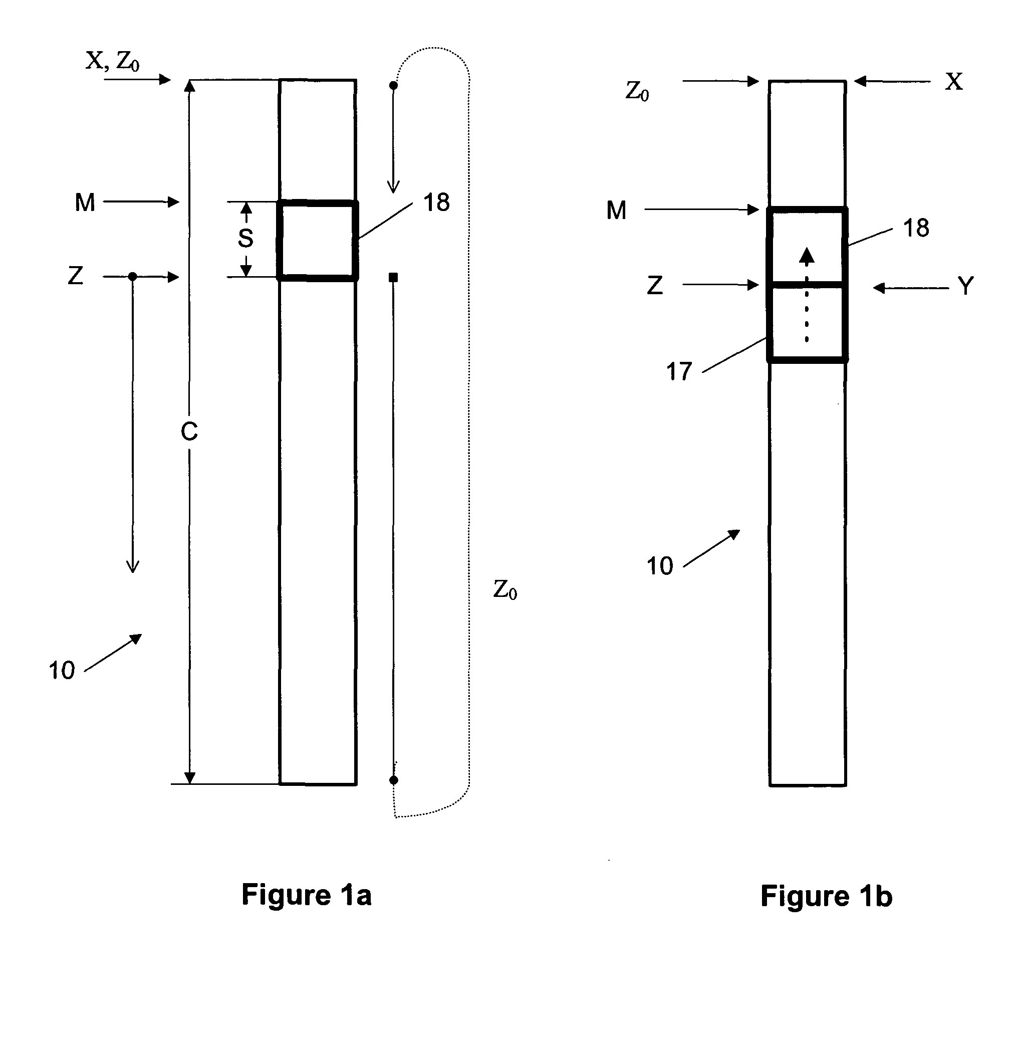
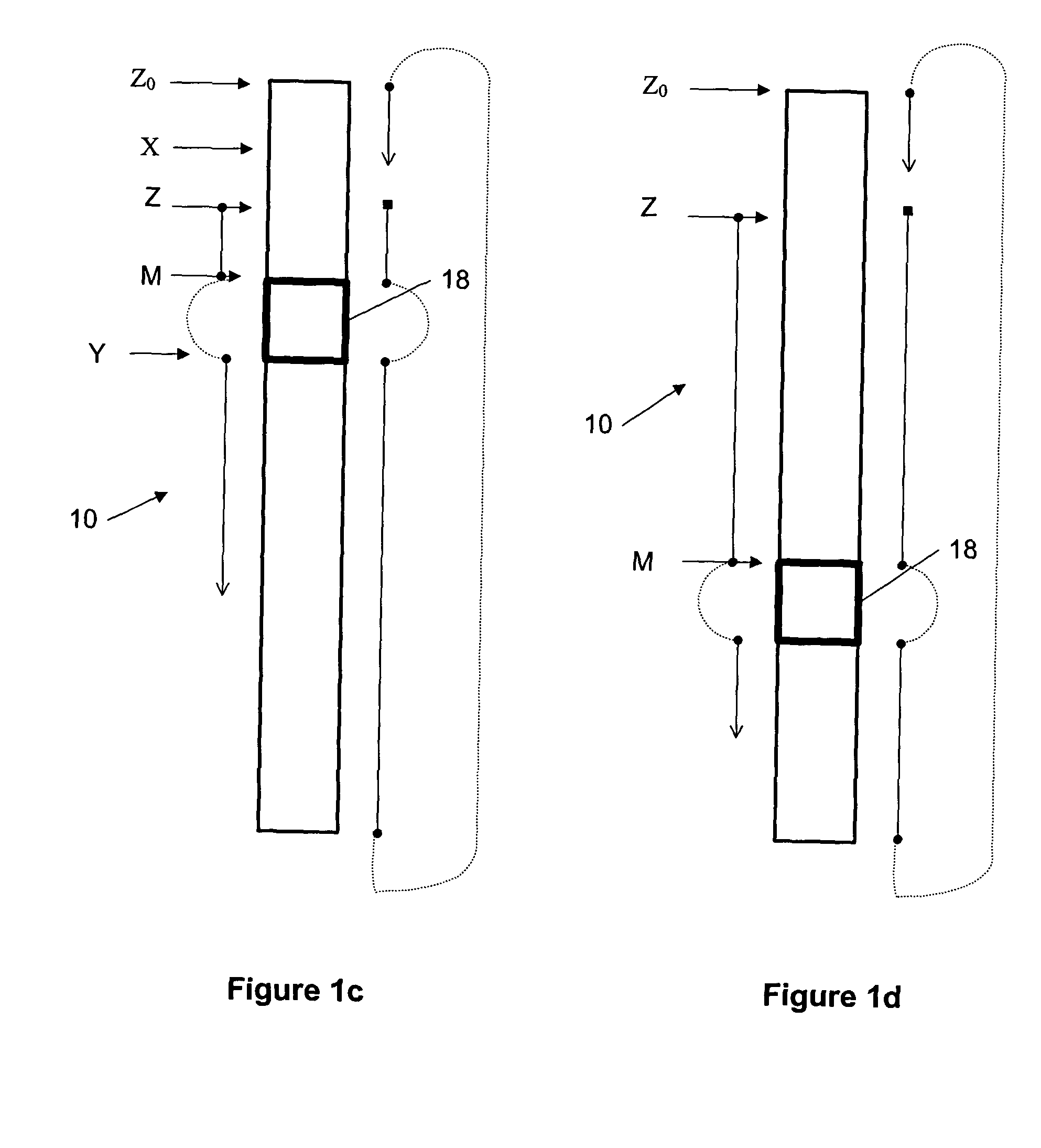
To assist in clarifying the technical subject matter of this invention, a few symbols are defined in Table 1 and further described in the text.

TABLE 1ReferenceSymbolDescriptionFIG.Z0A physical zero address / pointer, which isFIGS.always zero and pointing to the first memory1a-1d,element of the memory space 10 or 10u.FIG.2a-2c.ZA logical zero address / pointer; it is also calledFIGS.a second memory pointer.1a-1d,MA spare block address / pointer; it is also called aFIGS.first memory pointer.1a-1d,FIG. 2a.CA size of the memory 10 (a total number of theFIG. 1a.memory elements).SA size of the spare memory block 18 (a totalFIG. 1a.number of the memory elements in the spareblock).XA variable logical address of a memory elementFIGS.in the actual memory 10.1b-1c,FIG. 2a.X0,Logical pointers of the memory elements in theFIG. 2a.X2, . . . XC−1memory 10.UA variable logical address of a memory elementFIG. 2b.in the memory space 10u seen by the user.U1,Logical pointers of the memory elements in theFI...


PUM


Abstract

This invention describes a memory wear leveling for reducing wearing of hotspots (deteriorated memory blocks used more frequently) in all memory types by rotating the memory blocks on the physical level with the help of at least one spare memory block using predetermined criteria during both read and write operations. The invention can be implemented e.g. by using constant memory pointers at a logical level and dynamic memory pointers on the physical level. The rotation can be implemented as a combination of software and hardware functionalities or using hardware or software alone.

Description

FIELD OF THE INVENTION This invention generally relates to a memory wear leveling and more specifically to reducing wearing of hotspots (memory blocks used more frequently) by rotating the memory blocks on the physical level based on predetermined criteria using at least one spare memory block. BACKGROUND OF THE INVENTION Conventional memories (e.g. flash memories) deteriorate somewhat on each write operation (destructive write). This may cause problems if certain memory areas are written more often than other areas. This problem can be solved by maintaining registers that count the number of write operations performed for each memory block. The least used block is then selected as the next block to be used when data is written (so called “wear leveling”). Solutions for wear levelling are used, for example, in flash memories. These implementations typically use tables to store usage of given sectors. Typically, there are some spare blocks, which can be taken into use, and old bloc...

Claims


Application Information

Patent Timeline
Patent Type & Authority Applications(United States)
IPC IPC(8): G06F12/16
CPCG06F12/0246G06F2212/1036G11C16/3495G11C16/349G06F2212/7211
Inventor VIHMALO, JUKKA-PEKKAAHVENAINEN, MARKO T.MAKELA, JAKKE
Owner NOKIA SOLUTIONS & NETWORKS OY
Why Eureka
Try Eureka