Virtual disk drive system and method

a virtual disk and drive technology, applied in the direction of memory adressing/allocation/relocation, redundancy hardware error correction, instruments, etc., can solve the problems of not being required, system often needs bigger data storage space, and high cost of additional raid devices

Active Publication Date: 2005-03-10
DELL INT L L C
View PDF84 Cites 265 Cited by
  • Summary
  • Abstract
  • Description
  • Claims
  • Application Information

AI Technical Summary

Benefits of technology

[0012] Another advantage of the present invention is that the disk storage system controller is universal to any computer file system, not just to a specific computer file system.
[0013] The present invention also provides a method of data instant replay. In one embodiment, the data instant replay method includes the steps of: providing a default size of a logical block or disk storage block such that disk space of a RAID subsystem forms a page pool of storage or a matrix of disk storage blocks; automatically generating a snapshot of volumes of the page pool of storage or a snapshot of the matrix of disk storage blocks at predetermined time intervals; and storing an address index of the snapshot or delta in the page pool of storage or the matrix of the disk storage blocks such that the snapshot or delta of the matrix of the disk storage blocks can be instantly located via the stored address index.
[0014] The data instant replay method automatically generates snapshots of the RAID subsystem at user defined time intervals, user configured dynamic time stamps, for example, every few minutes or hours, etc., or time directed by the server. In case of a system failure or virus attack, these time-stamped virtual snapshots allow data instant replay and data instant recovery in a matter of a few minutes or hours, etc. The technique is also referred to as instant replay fusion, i.e

Problems solved by technology

In addition, the systems often need bigger data storage space whereby more RAID devices are added.
However, often ti

Method used


Image

  • Virtual disk drive system and method
  • Virtual disk drive system and method
  • Virtual disk drive system and method

Examples


Embodiment Construction

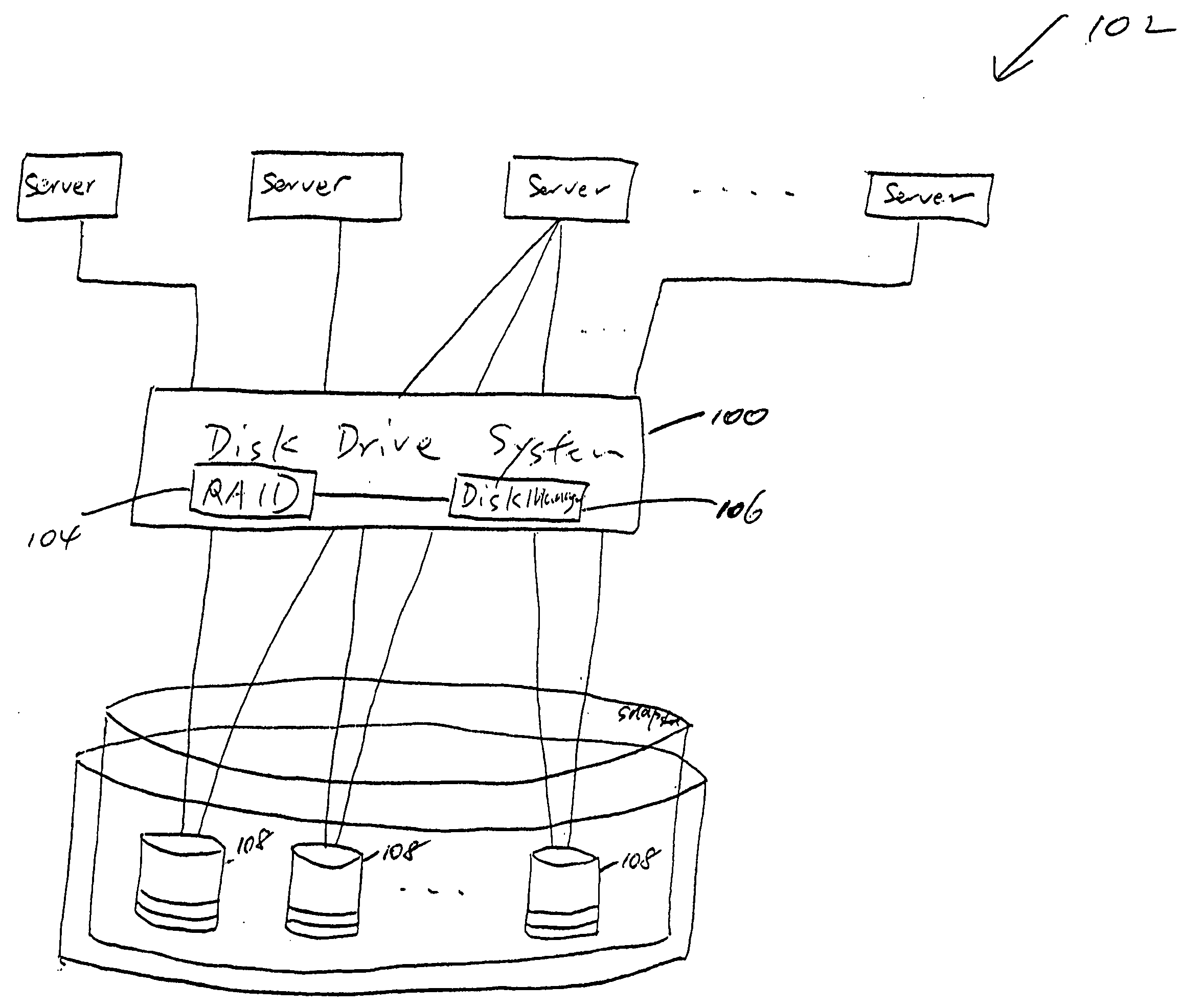
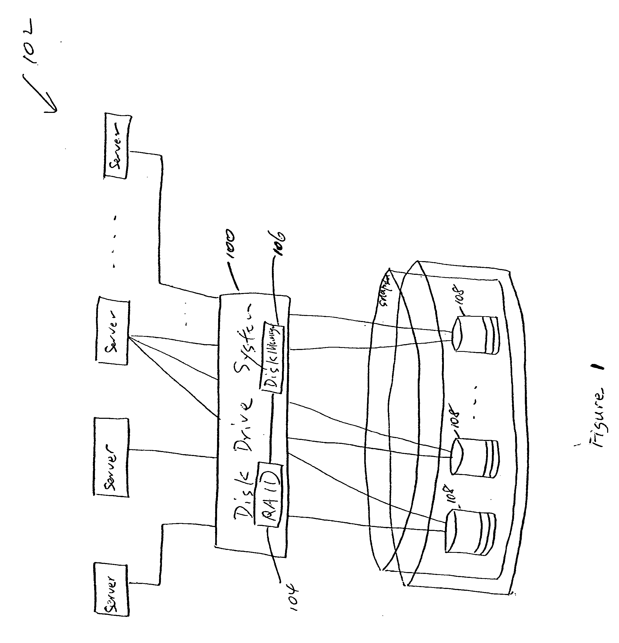
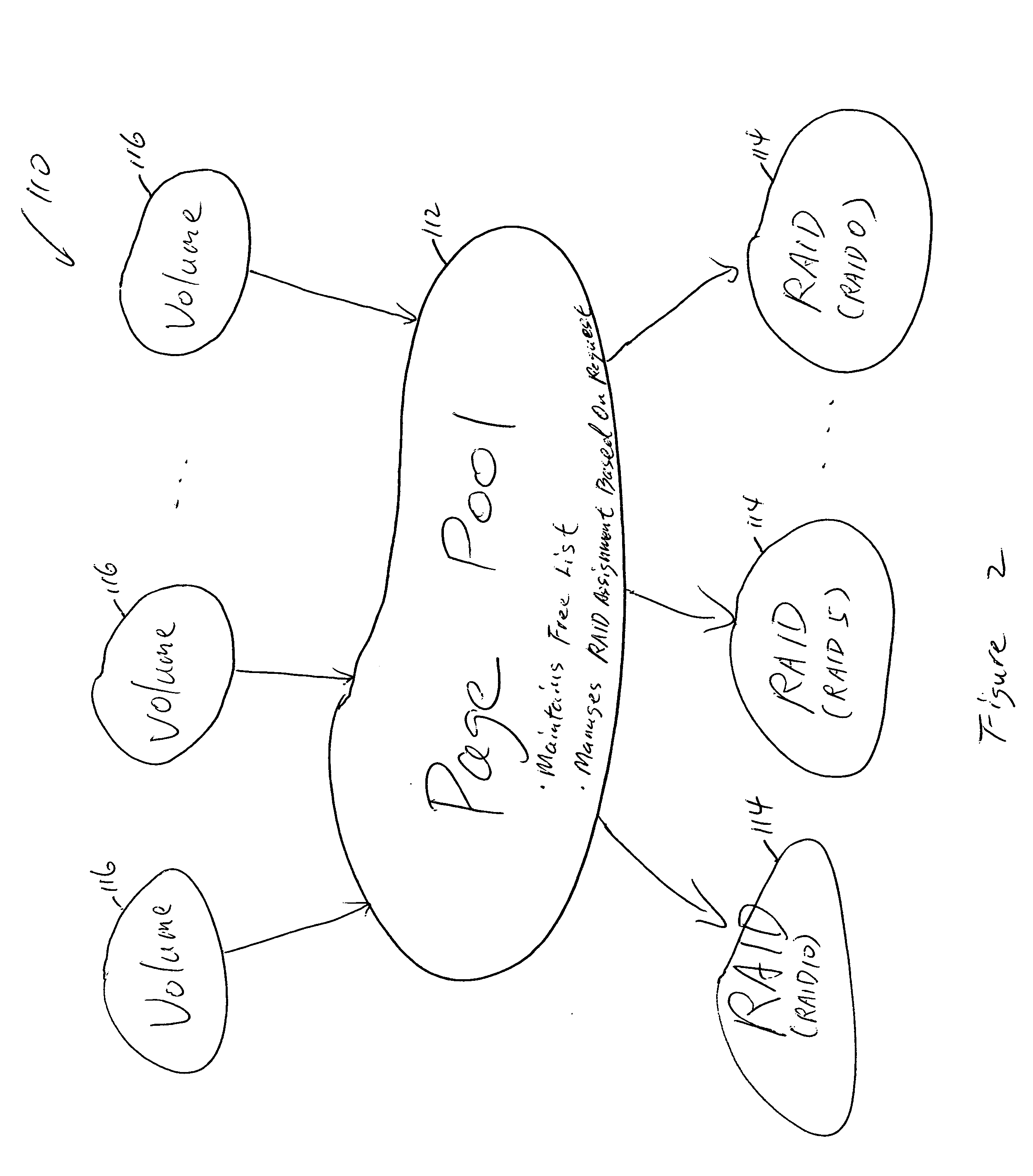
[0054] The present invention provides an improved disk drive system and method capable of dynamically allocating data. The disk drive system may include a RAID subsystem having a page pool of storage that maintains a free list of RAIDs or alternatively, a matrix of disk storage blocks, and a disk manager having at least one disk storage system controller. The RAID subsystem and disk manager dynamically allocate data across the page pool of storage or the matrix of disk storage blocks and a plurality of disk drives based on RAID-to-disk mapping. The RAID subsystem and disk manager determine whether additional disk drives are required, and a notification is sent if the additional disk drives are required. Dynamic data allocation allows a user to acquire a disk drive later in time when it is needed. Dynamic data allocation also allows efficient data storage of snapshots / point-in-time copies of virtual volume matrix or pool of disk storage blocks, instant data replay and data instant fu...


PUM


Abstract

A disk drive system and method capable of dynamically allocating data is provided. The disk drive system may include a RAID subsystem having a pool of storage, for example a page pool of storage that maintains a free list of RAIDs, or a matrix of disk storage blocks that maintain a null list of RAIDs, and a disk manager having at least one disk storage system controller. The RAID subsystem and disk manager dynamically allocate data across the pool of storage and a plurality of disk drives based on RAID-to-disk mapping. The RAID subsystem and disk manager determine whether additional disk drives are required, and a notification is sent if the additional disk drives are required. Dynamic data allocation and data progression allow a user to acquire a disk drive later in time when it is needed. Dynamic data allocation also allows efficient data storage of snapshots/point-in-time copies of virtual volume pool of storage, instant data replay and data instant fusion for data backup, recovery etc., remote data storage, and data progression, etc.

Description

CROSS-REFERENCE TO RELATED APPLICATION(S) [0001] The present utility patent application claims priority of U.S. Provisional Patent Application Ser. No. 60 / 495,204, filed Aug. 14, 2003; subject matter of which is incorporated herewith by reference.FIELD OF THE INVENTION [0002] The present invention generally relates to a disk drive system and method, and more particularly to a disk drive system having capabilities such as dynamic data allocation and disk drive virtualization, etc. BACKGROUND OF THE INVENTION [0003] The existing disk drive systems have been designed in such a way that a virtual volume data storage space is statically associated with physical disks with specific size and location for storing data. These disk drive systems need to know and monitor / control the exact location and size of the virtual volume of data storage space in order to store data. In addition, the systems often need bigger data storage space whereby more RAID devices are added. However, often times th...

Claims


Application Information

Patent Timeline
IPC IPC(8): G06F3/06G06F11/00G06F11/14G06F11/20
CPCG06F3/0608G06F3/0631G06F3/0665G06F3/067G06F3/0689G06F11/108G06F11/1461G06F11/1471G06F11/2089G06F2201/84G06F12/02G06F11/1435G06F3/0611G06F3/0647G06F3/0683G06F3/0619G06F3/064G06F3/065G06F3/0659
Inventor SORAN, PHILIP E.GUIDER, JOHN P.ASZMANN, LAWRENCE E.KLEMM, MICHAEL J.
Owner DELL INT L L C
Why Eureka
Try Eureka