Microfluidic inkjet control method

a microfluidic inkjet and control method technology, applied in the direction of coatings, printing, other printing apparatuses, etc., can solve the problems of low performance efficiency, color mixing, and generic inkjet production method of color filter or organic pled, and achieve the effect of reducing the probability of satellite droplet production

Inactive Publication Date: 2005-03-17
IND TECH RES INST
View PDF7 Cites 8 Cited by
  • Summary
  • Abstract
  • Description
  • Claims
  • Application Information

AI Technical Summary

Benefits of technology

To improve the known technology, the invention provides a microfluidic inkjet control method that is applicable to thermal print heads.

Problems solved by technology

However, the generic inkjet production method for color filters or organic PLED has a major problem caused by the satellite ink droplets that accompany the main ink droplets.
This behavior causes serious problems, such as color mixing and low performance efficiency.
However, if the nozzle is too close to the printing substrate, it is easy to scratch the substrate.
On the other hand, if the distance is too short, the ink drops may not be able to break-off completely, so they are dragged on the substrate; this can cause the main droplets to be shifted from the predetermined position and color mixing.
Since the density of ink increases as it is heated, the size of the ink droplet becomes inconsistent, and it may even influence the deviation straightness of the ink and make the satellite droplets problem worse.
As described in U.S. Pat. No. 6357846, when the nozzle is idl

Method used


Image

  • Microfluidic inkjet control method
  • Microfluidic inkjet control method
  • Microfluidic inkjet control method

Examples


Embodiment Construction

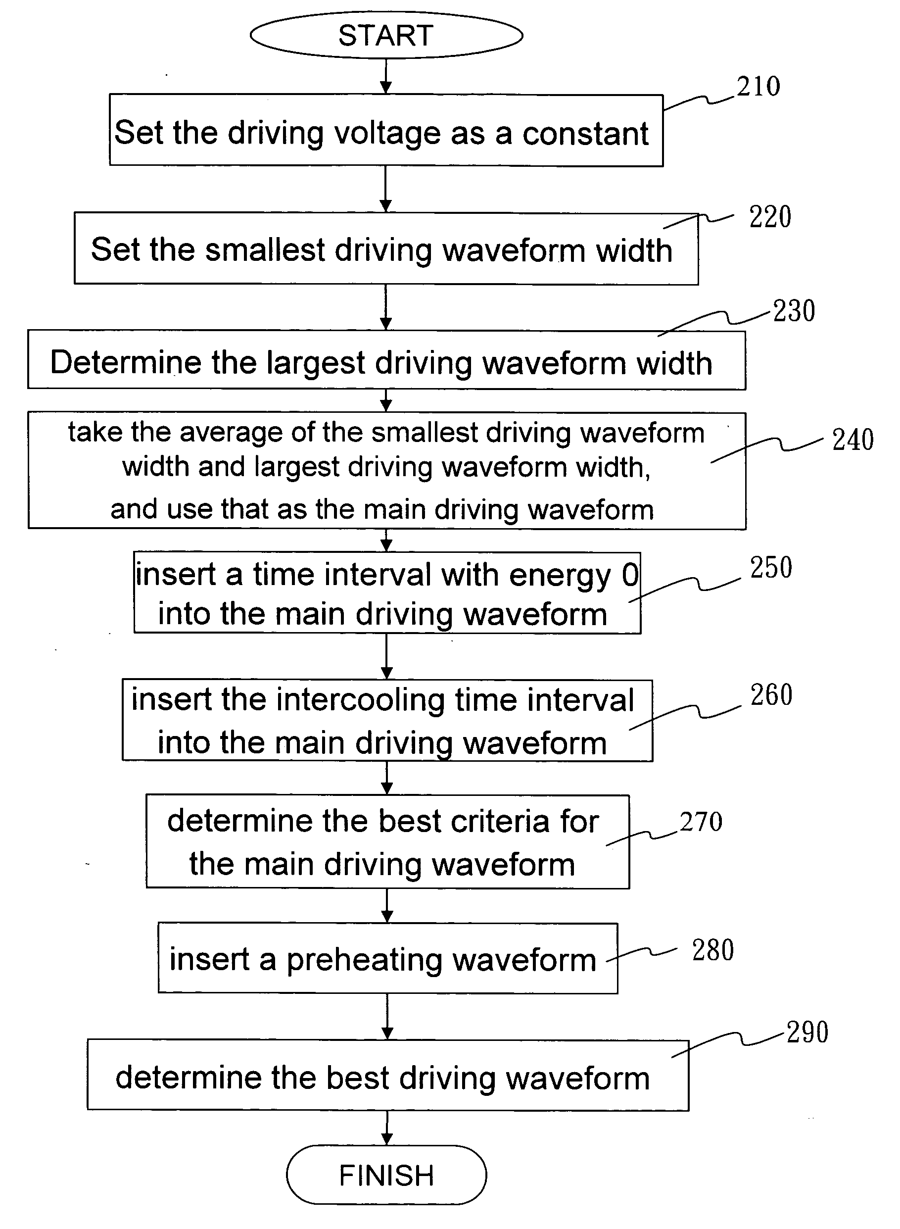
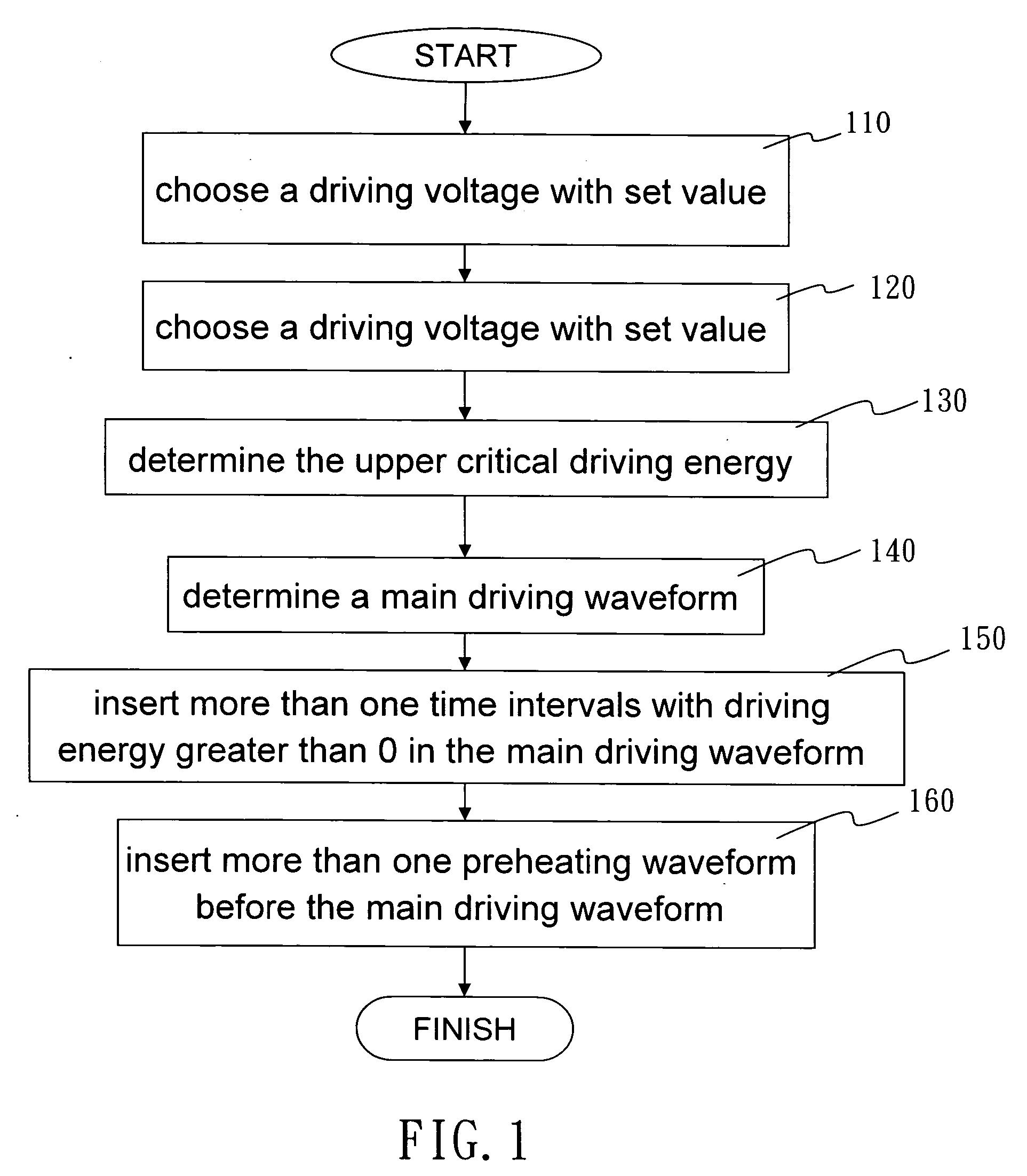
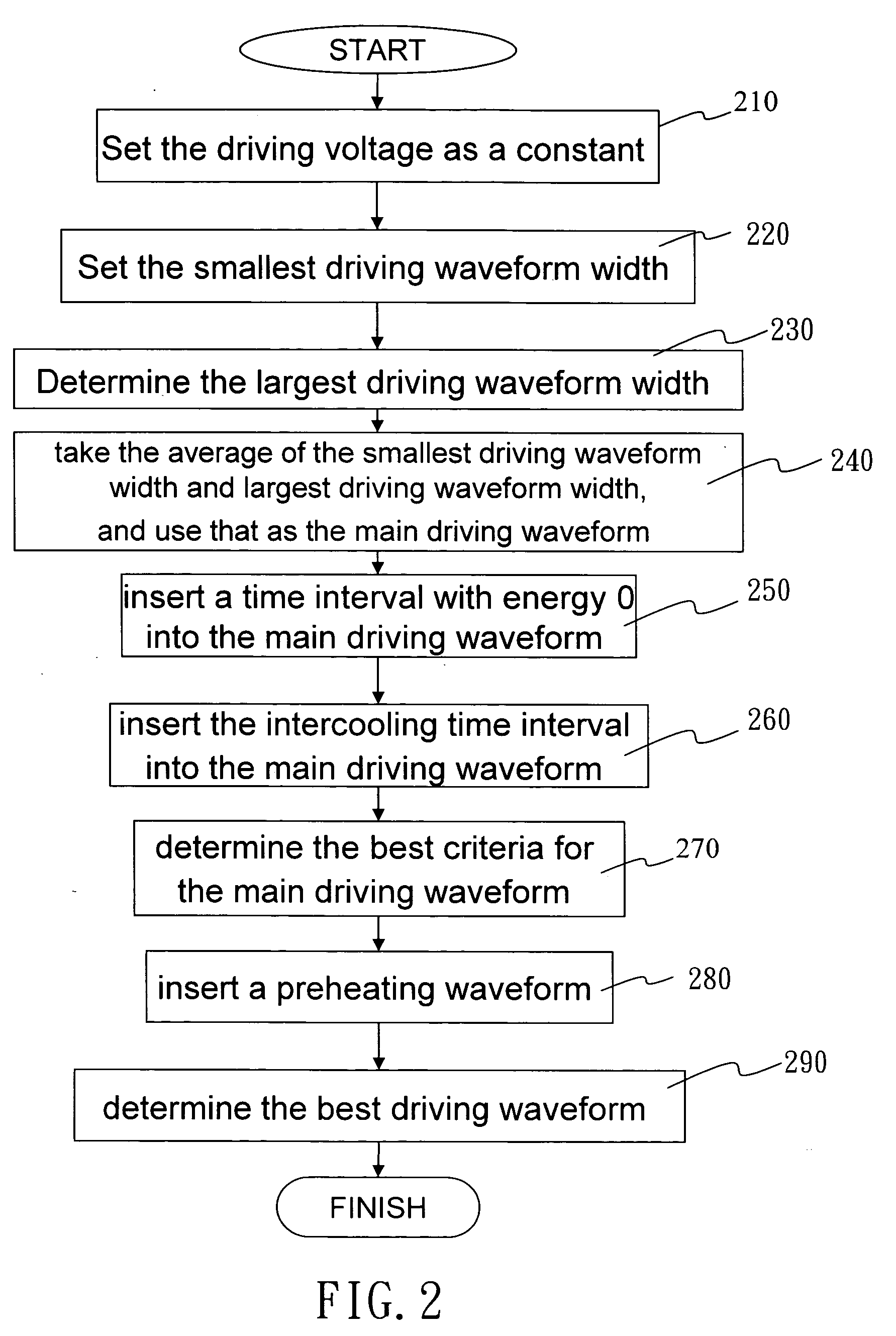
The invention adjusts the driving waveform, to reduce the satellite droplets, accompanying the main droplet during the ink ejecting process. When ink is heated at the nozzle, microbubbles appear; at this time, extending the time period between the heating and the ejecting of the ink, and intercooling stages are inserted. The intercooling stages can extend the time period between heating and ejecting of the ink, so that more microbubbles are produced constructing more complete and stronger bubbles and increasing the force that ejects the ink droplets out of the nozzle. The ejecting property of the ink droplet is improved as the ejection velocity is increased and the flying deviation of the ink droplet is decreased, so the satellite droplets are reduced. A preheating stage waveform, which increases the stability of the ink ejection, is also inserted before the main driving waveform. Preheating can keep the shape of the original shapes of the ink droplets consistent before they are ej...


PUM


Abstract

A microfluidic inkjet control method, by adjusting the driving waveform of the print head, including intercooling waveform and pre-heating waveform, to reduce the satellite droplets produced accompany the main ink droplets during the inkjet printing process. After entering the parameters, the control method uses a print head module with nozzles with adjustable rotating angle and calculates the needed nozzle sequence and appropriate time delay to control the print head module and determine the operation of each nozzle. This achieves the goal of printing different types of elements.

Description

BACKGROUND OF THE INVENTION 1. Field of Invention The present invention relates to a microfluidic inkjet control method, especially a microfluidic inkjet control method that is used to adjust the inkjet waveforms of the thermal print heads. 2. Related Art Inkjet printing technology uses precision element printing that is applicable to many different materials. It satisfies electronic industry's precision element production demands of automation, is more compact, has lower costs, has a faster production time and reduces the impact on the environment. For example: application on the color filters on the liquid crystal display panel and the organic polymer light emitter diode, PLED, production. The color filter is composed of red, green and blue colors, spread on the substrate and also the black matrixes between the color ink. The inkjet printing process is to spread the ink droplets directly on the concavities formed by the black matrixes on the color filter substrate. Different t...

Claims


Application Information

Patent Timeline
IPC IPC(8): B05D1/26B41J2/01B05D3/00B41J2/05H01L51/50H05B33/10
CPCB41J2/04516B41J2/04528B41J2/04598B41J2/0458B41J2/04596B41J2/04573
Inventor CHENG, KEVINHO, YUNG-KUO
Owner IND TECH RES INST
Why Eureka
Try Eureka