Light source and vehicle lamp

a technology for vehicle lamps and led light sources, which is applied in the field of light sources, can solve the problems of low light utilization efficiency, difficult to form a clear cutoff without using the light shielding plate, and difficult to configure led light sources as vehicle headlights, etc., to achieve the effect of eliminating chromaticity deviation, reducing the temperature rise of the fluorescent substance layer, and reducing the cost of production

Active Publication Date: 2005-03-17
STANLEY ELECTRIC CO LTD
View PDF34 Cites 80 Cited by
  • Summary
  • Abstract
  • Description
  • Claims
  • Application Information

AI Technical Summary

Benefits of technology

[0060] Thus, by allowing light from the LED chip to fall on the fluorescent substance layer that is isolated from the LED chip, exciting the fluorescent substance in the fluorescent substance layer, emitting mixed color light outside the light source apparatus via the light shielding portion and projecting the light forward with the projection lens, it is possible to suppress temperature rise in the fluorescent substance layer for improved utilization efficiency

Problems solved by technology

However, use of a large-current type white LED light source as a light source for a vehicle headlight presents problems as described below, making it difficult to actually configure the LED light source as a vehicle headlight.
This results in approximately 30 to 40% of light from the white LED light source 1 being blocked by the light shielding plate 8b or 9b, thus considerably lowing light utilization efficiency.
However, the emission shape of the white LED light source 1 is rectangular or circular, making it difficult to form a clear cutoff without using the light shielding plate 8b or 9b.
Therefore, it is difficult for LED light sources that are less bright than the existing halogen light bulbs or HIBs to achieve a peak luminous intensity value.
Additionally, the LED light source becomes as deep in structural volume requirements as the existing projector type lamp due to difficulties involved in making use of surface emission (the advantage of the LED light

Method used


Image

  • Light source and vehicle lamp
  • Light source and vehicle lamp
  • Light source and vehicle lamp

Examples


Embodiment Construction

[0093] Preferred embodiments of the present invention will now be described in detail with reference to FIGS. 1 to 21.

[0094] It should be noted that while the embodiments described below are subject to various technically preferred limitations because they are preferred specific examples, the scope of the present invention may not be limited thereby.

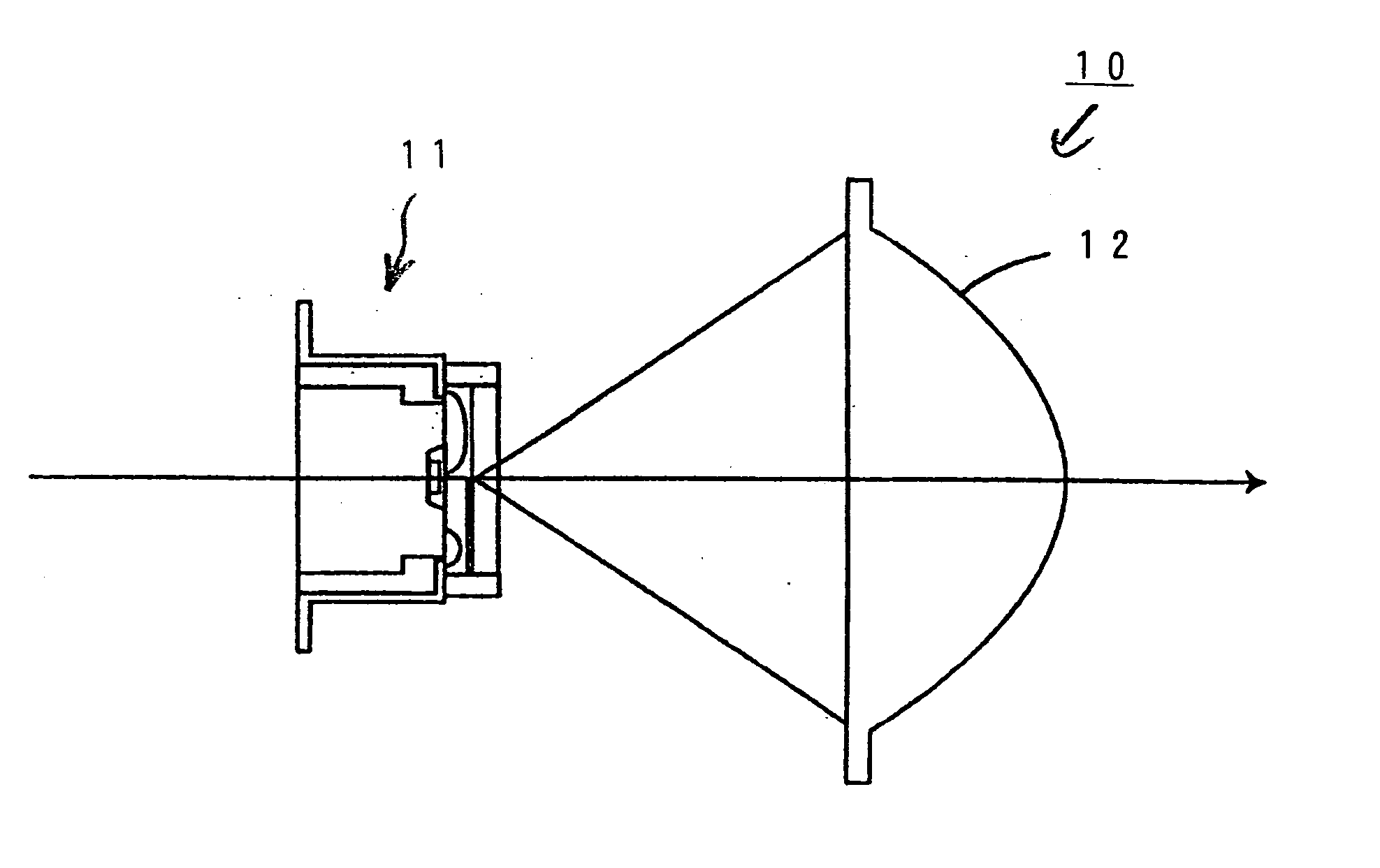
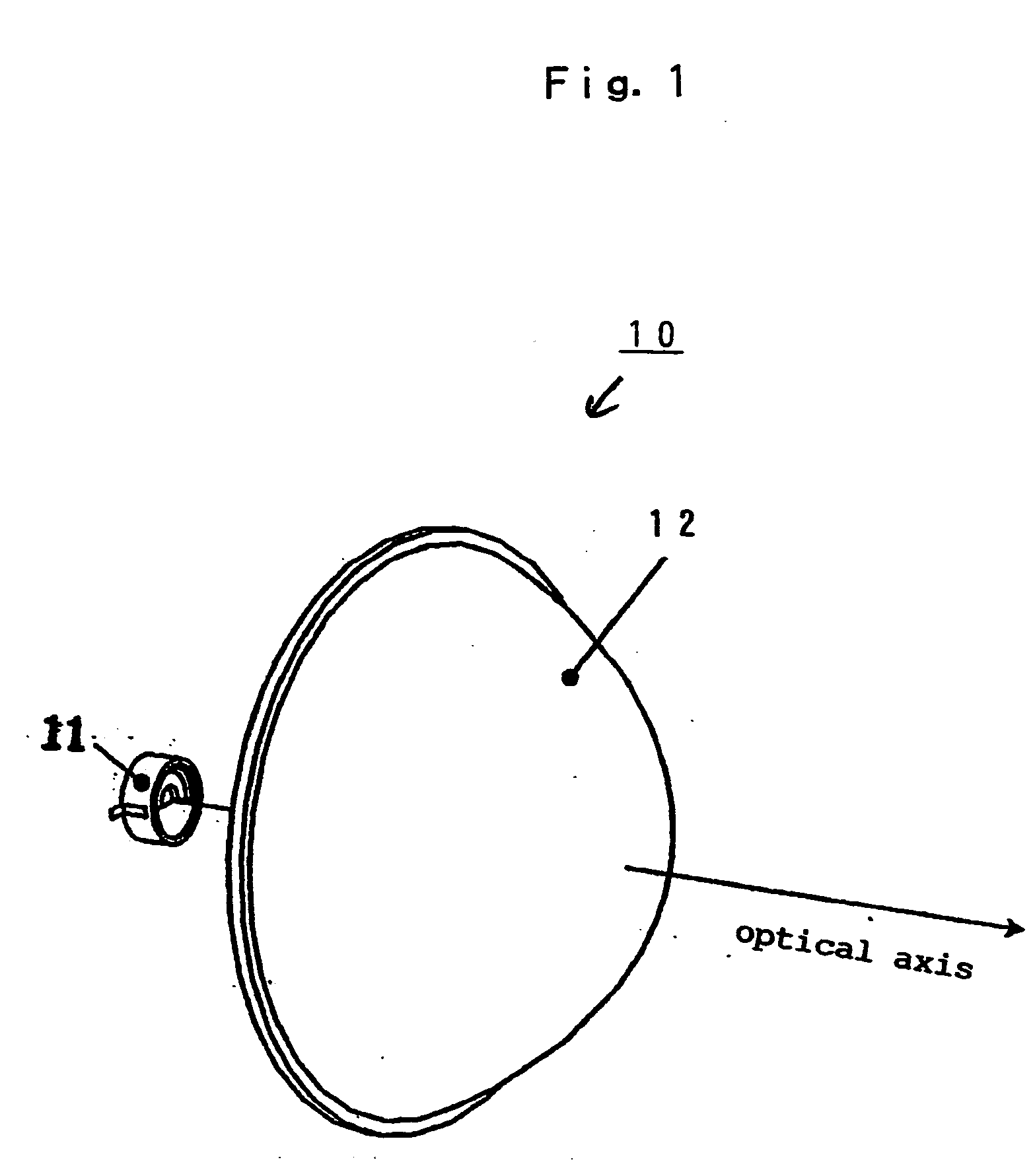
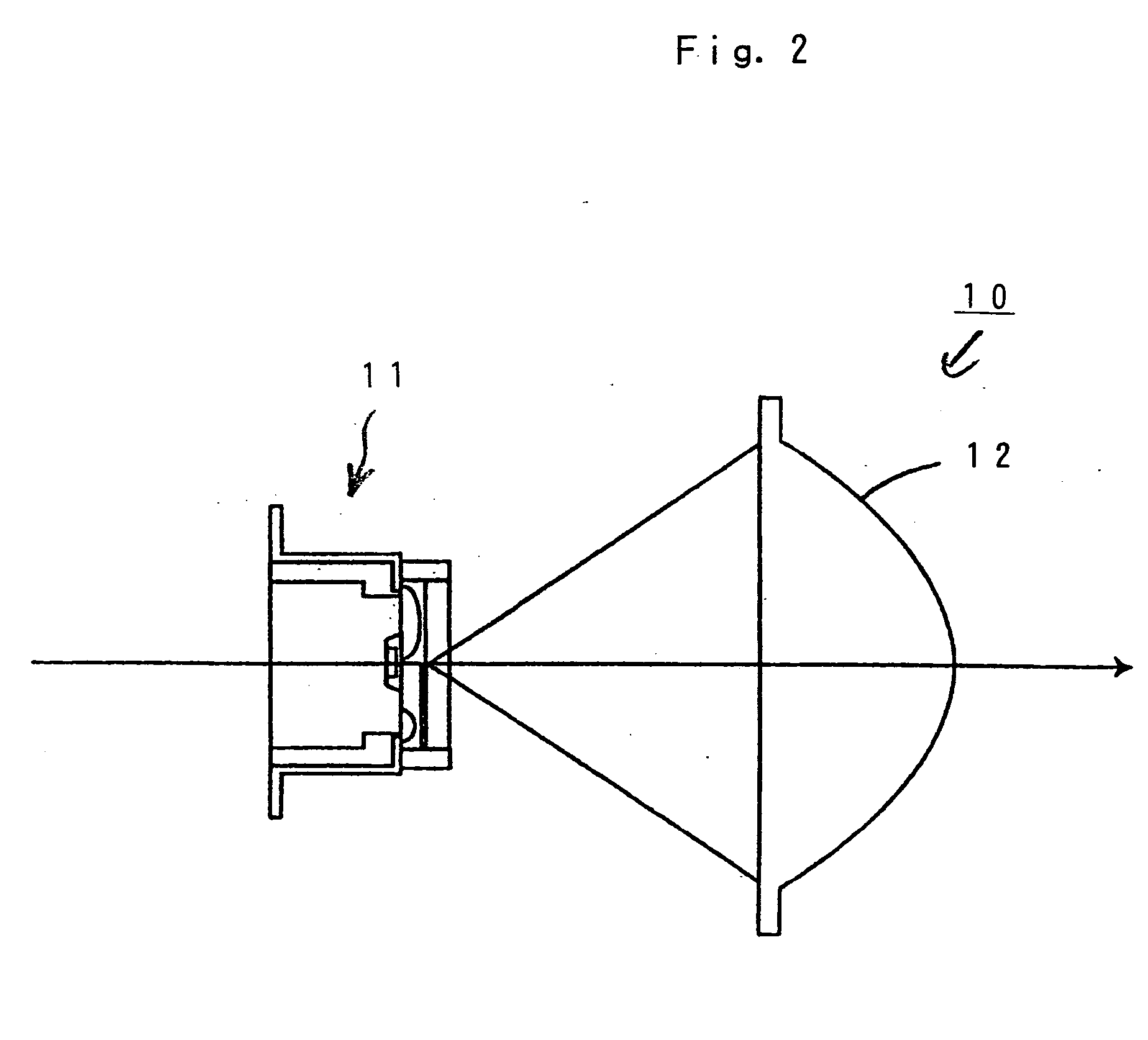
[0095] FIGS. 1 to 3 illustrate a configuration of a preferred embodiment of a light source made in accordance with the principles of the present invention.

[0096] In FIGS. 1 and 2, the light source is configured as a vehicle headlight 10 that can include a light source apparatus 11 and a projection lens 12 for converging light from the light source apparatus 11. The light source apparatus 11 can include a base 20, an LED chip 21, a resin portion 22, an optical member 23, a light shielding portion 24, a fluorescent substance layer 25 and a pair of lead terminals 26 and 27, as shown in FIGS. 4 and 5.

[0097] The base 20 can be constituted...


PUM


Abstract

A light source for vehicles can include a base having a cavity formed on its upper surface, an LED chip mounted in the cavity of the base, a resin portion for sealing the LED chip in the cavity, an optical member disposed above the base and apart from the LED chip, a light shielding portion disposed on the inner surface of the optical member and which forms a cutoff suited for a light distribution pattern, and a fluorescent substance layer disposed at least in regions other than the light shielding portion on the inner surface of the optical member.

Description

[0001] This invention claims the benefit of Japanese Patent Application No. 2003-323820, filed on Sep. 17, 2003, which is hereby incorporated by reference. [0002] 1. Field of the Invention [0003] The present invention relates to a light source and more particularly to a light source apparatus for vehicle lamps employing a plurality of LED elements and to a vehicle lamp such as a headlight and an auxiliary headlight using the light source apparatus. [0004] 2. Description of the Related Art [0005] Conventional large-current type white LED light sources are configured, for example, as shown in FIG. 22. In FIG. 22, a white LED light source 1 includes an LED chip 3 mounted in a cavity 2a provided on the upper surface of a heat radiating core 2. A resin 4 containing fluorescent substance such as silicon or epoxy can be located on the heat radiating core 2 and include a lens 5 located above the resin 4. Drive current can be supplied to the LED chip 3 by wire-bonding the upper ends of lead ...

Claims


Application Information

Patent Timeline
IPC IPC(8): F21S8/10F21S8/12F21V5/00F21V7/00F21V7/09F21V11/00F21V11/16F21V29/00F21W101/10F21Y101/00F21Y101/02
CPCF21S48/115F21S48/145F21Y2101/02H01L33/507H01L33/58H01L33/60Y10S362/80H01L2224/48091H01L2224/45144H01L2924/19107H01L2924/00014H01L2924/00F21Y2115/10F21S41/143F21S41/16F21S41/176F21S41/43
Inventor YATSUDA, YASUSHIHARADA, MITSUNORI
Owner STANLEY ELECTRIC CO LTD
Why Eureka
Try Eureka