
Controlled synchronous rectifier for controlling an output voltage of a switched mode power supply

a technology of synchronous rectifiers and power supply voltages, which is applied in the direction of electric variable regulation, process and machine control, instruments, etc., can solve the problems of complex and cost-intensive circuitry, the residual ripple of output voltage is then adjusted, and the requirements of safety standards are problematic. , to achieve the effect of high residual rippl

Inactive Publication Date: 2005-03-17
FRIWO MOBILE POWER GMBH
View PDF5 Cites 15 Cited by
  • Summary
  • Abstract
  • Description
  • Claims
  • Application Information

AI Technical Summary

Benefits of technology

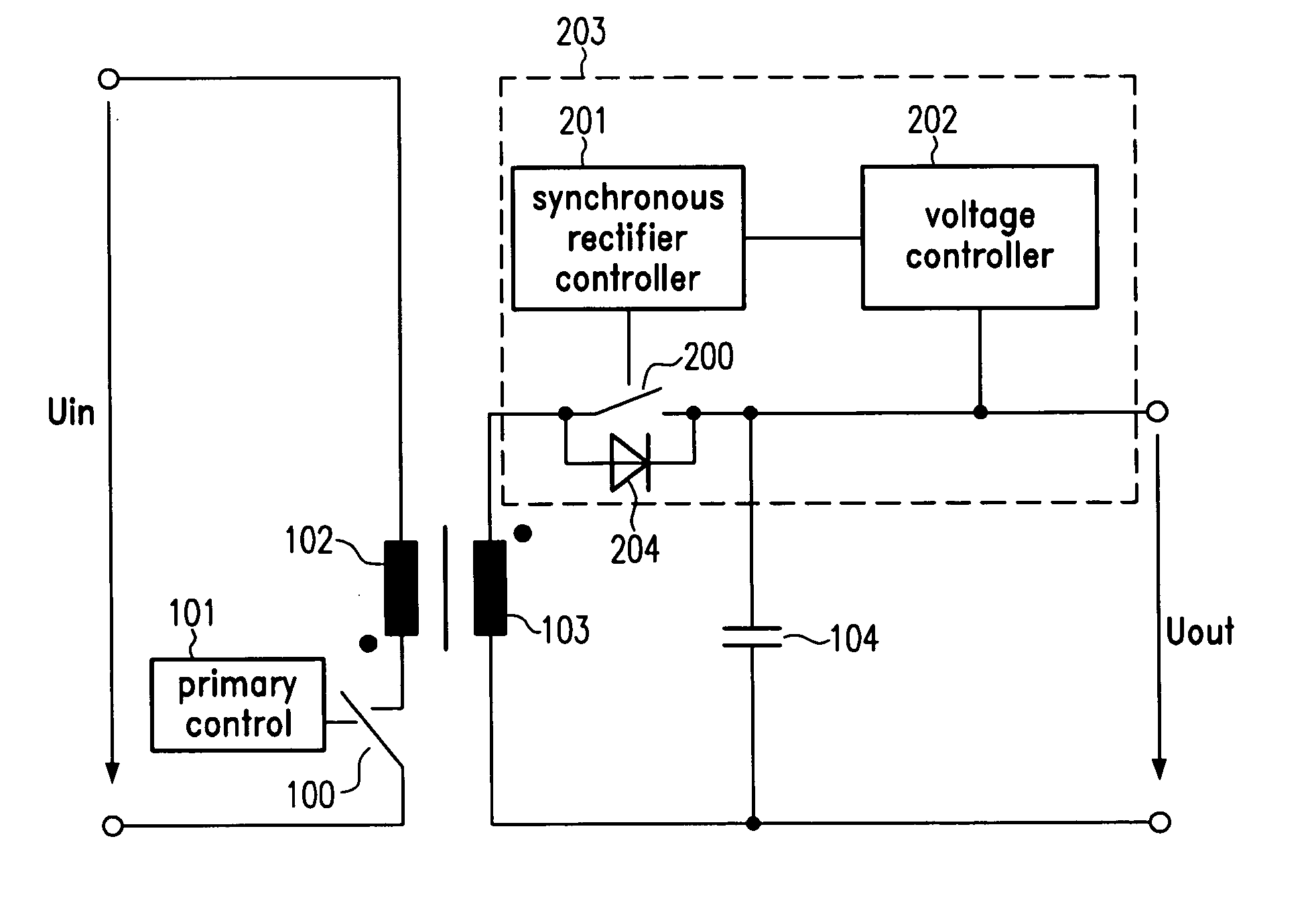
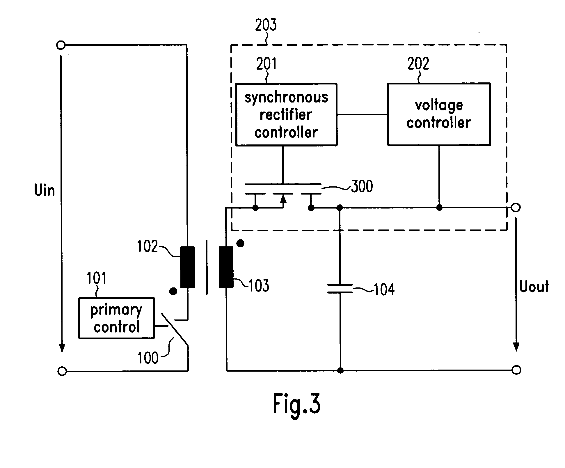
[0017] The present invention is based on the finding that, in the case of insufficient smoothing of the output voltage, an inadmissibly high residual ripple of the output voltage can be compensated by the use of a secondary-side control circuit. Such a control circuit for controlling an output voltage of a switched mode power supply is provided according to one embodiment of the present invention. The switched mode power supply comprises a primary-side switch and a transformer with a primary winding and a secondary winding. The output voltage is adapted to be tapped at a capacitor which is connected in parallel to the secondary winding. The control circuit is adapted to be connected to a connection of the capacitor and to a connection of the secondary winding, said control circuit being a controllable synchronous rectifier, wherein no feedback connection between the secondary side to the primary side is required. The advantage of said controllable synchronous rectifier is that it can be used both in primary-controlled as well as in secondary-controlled switched mode power supplies for an analogue readjustment of residual ripples of the output voltages.
[0018] According to a further embodiment, the control circuit comprises a secondary-side switch with a parallel diode which is connected thereto in parallel, said secondary-side switch with the parallel-connected parallel diode being adapted to be connected to the secondary winding. The control circuit additionally comprises a synchronous rectifier controller for controlling the secondary-side switch, and a voltage control unit for controlling a turn-on level of said synchronous rectifier controller in dependence upon the output voltage. This arrangement is advantageous insofar the secondary-side switch can be controlled without having to use auxiliary windings, e.g. for providing reference voltages or other auxiliary voltages.

Problems solved by technology

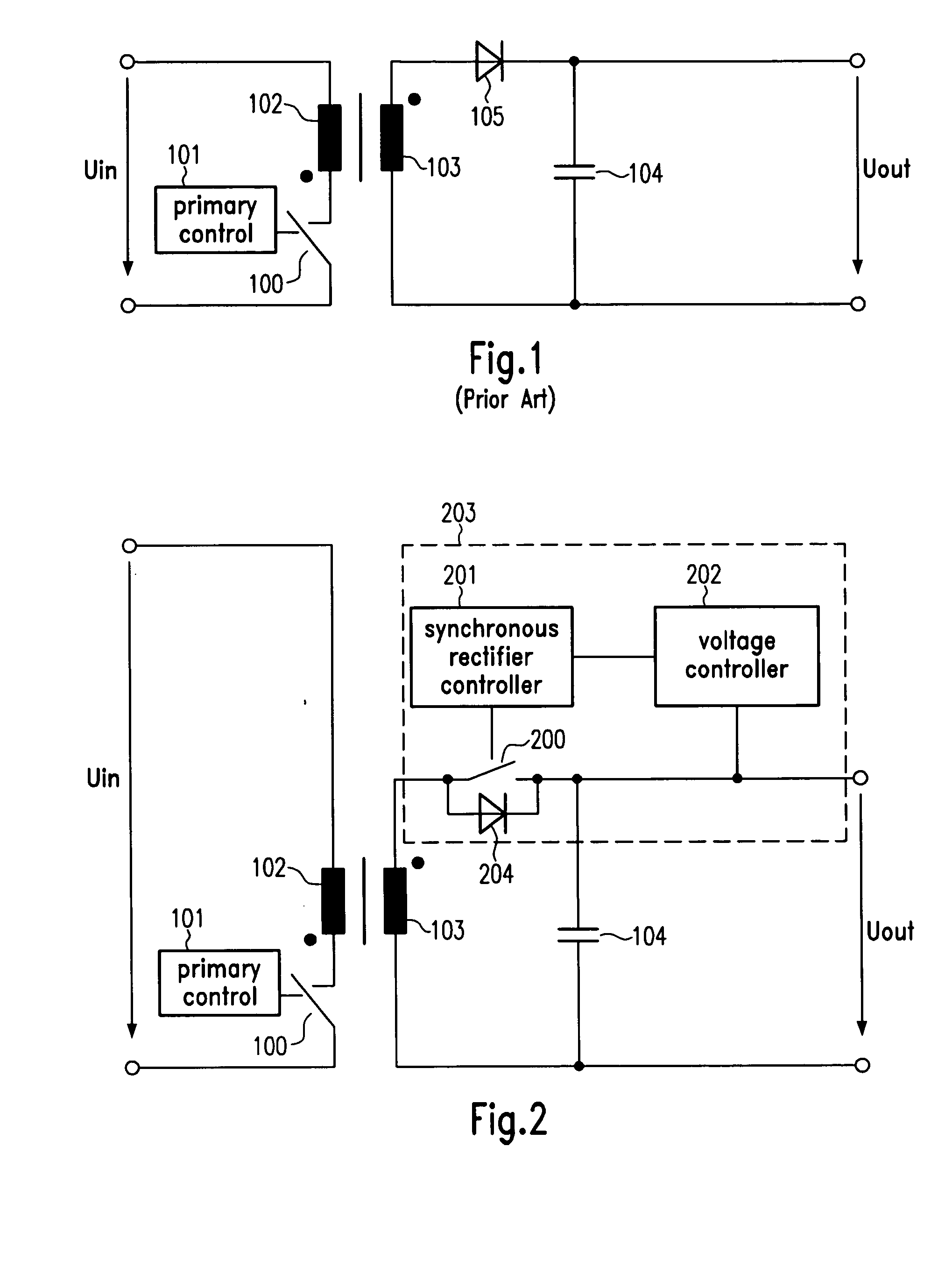
The secondary-side arrangement of the rectifier diode 105 and of the smoothing capacitor 104 proves, however, insufficient in some cases, a readjustment of the residual ripple of the output voltage being then necessary.
), however, has the problem that the necessary circuitry is rather complex and cost-intensive.
Moreover, as a connection between the secondary and the primary side of the transformator via the gate drive circuit is needed, the requirements which have to be met with respect to safety standards are problematic.

Method used


Image

  • Controlled synchronous rectifier for controlling an output voltage of a switched mode power supply
  • Controlled synchronous rectifier for controlling an output voltage of a switched mode power supply
  • Controlled synchronous rectifier for controlling an output voltage of a switched mode power supply

Examples


Embodiment Construction

[0024] The illustrated embodiments of the present invention will be described with reference to the figure drawings wherein like elements and structures are indicated by like reference numbers.

[0025] Referring now to the drawings and in particular to FIG. 2 which is a circuit diagram of a simple realization of a primary-clocked conventional switched mode power supply, a control circuit 203 for controlling the output voltage of a primary-controlled switched mode power supply is shown in its application environment. The control circuit 203 comprises a secondary-side switch 200 and a parallel-connected parallel diode 204, said switch 200 being adapted to be connected to the secondary winding 103, a synchronous rectifier controller 201 for controlling the secondary-side switch and a voltage control unit 202 for controlling a turn-on level of the synchronous rectifier controller in dependence upon the output voltage Uout. The secondary-side switch 200 and the parallel-connected parallel...


PUM


Abstract

The present invention relates to a control circuit for controlling the output voltage of a switched mode power supply which comprises a primary-side switch and a transformer with a primary winding and a secondary winding. The output voltage of the switched mode power supply is adapted to be tapped at a capacitor which is connected in parallel to said secondary winding. The control circuit is adapted to be connected to a connection of the capacitor and a connection of the secondary winding, said control circuit being a controllable synchronous rectifier. Making use of this control circuit, an improved control accuracy can be achieved and an existing residual ripple of the output voltage can be compensated.

Description

BACKGROUND OF THE INVENTION [0001] 1. Field of the Invention [0002] The present invention relates generally to control circuits for controlling the output voltage of a switched mode power supply. In particular, the present invention relates to a control circuit in a primary-controlled switched mode power supply, which comprises a primary-side switch and a transformer with a primary winding and a secondary winding, the output voltage being adapted to be tapped at a capacitor which is connected in parallel to said secondary winding. The present invention additionally relates to a switched mode power supply for generating an output voltage, said switched mode power supply making use of the control circuit. Furthermore, the present invention concerns a method of controlling an output voltage of a switched mode power supply. [0003] 2. Description of the Related Art [0004] Switched mode power supplies are clocked power supply units which chop a rectified, filtered mains voltage. Such swit...

Claims


Application Information

Patent Timeline
IPC IPC(8): H02M3/28H02M3/335
CPCY02B70/1475H02M3/33592Y02B70/10
Inventor BERGHEGGER, RALF SCHRODER GEN.
Owner FRIWO MOBILE POWER GMBH
Learn More