Thermal development method and apparatus

a technology of applied in the field of thermal development method and apparatus, can solve the problems of color tarnishing, color tone displacement, lag in heat travel to a non-heated image formation layer, etc., and achieve the effect of reducing heat conductivity, reducing heat conductivity, and equal development efficiency

Inactive Publication Date: 2005-03-17
FUJIFILM HLDG CORP +1
View PDF3 Cites 5 Cited by
  • Summary
  • Abstract
  • Description
  • Claims
  • Application Information

AI Technical Summary

Benefits of technology

The present invention has been conceived in view of the circumstances and aims at providing a thermal development method and apparatus capable of preventing occurrence of crimps and capable of subjecting both sides of the recording material to uniform thermal development, as well as capable of preventing occurrence of a color tone displacement and variations in density.
In this thermal development apparatus, the photosensitive photothermographic recording material is transported while being nipped between a pair of endless belts disposed along the conveyance path of the photosensitive photothermographic recording material. The amount of heat originating from the endless belt having higher heat conductivity is suppressed so as to become smaller than the amount of heat originating from the remaining endless belt having lower heat conductivity, whereby equal development efficiency is attained. Accordingly, uniform heating of the two surfaces becomes feasible, and a temperature difference is eliminated. By means of this configuration, the pair of endless belts is rotated in synchronism with transportation of the photosensitive photothermographic recording material, so that no rubbing arises between the heating unit and the photosensitive photothermographic recording material.

Problems solved by technology

However, when a related-art thermal development apparatus which heats only one side of the recording material is used for a recording material having an image formation layer provided on either side of the film, a lag arises in travel of heat to a non-heated image formation layer.
Such a lag in development causes a color tone displacement; i.e., tarnishing of colors of the image formation layer.
Moreover, when sufficient heat has failed to travel to the non-heated image formation layer, development is insufficient, to thus cause variations in density, such as a reduction in density.
Moreover, when both sides of the recording material having the image formation layers provided thereon are subjected to abrupt heating, there arises a problem of occurrence of crimps in the recording material.

Method used


Image

  • Thermal development method and apparatus
  • Thermal development method and apparatus
  • Thermal development method and apparatus

Examples


first embodiment

(Embodiment 1-1)

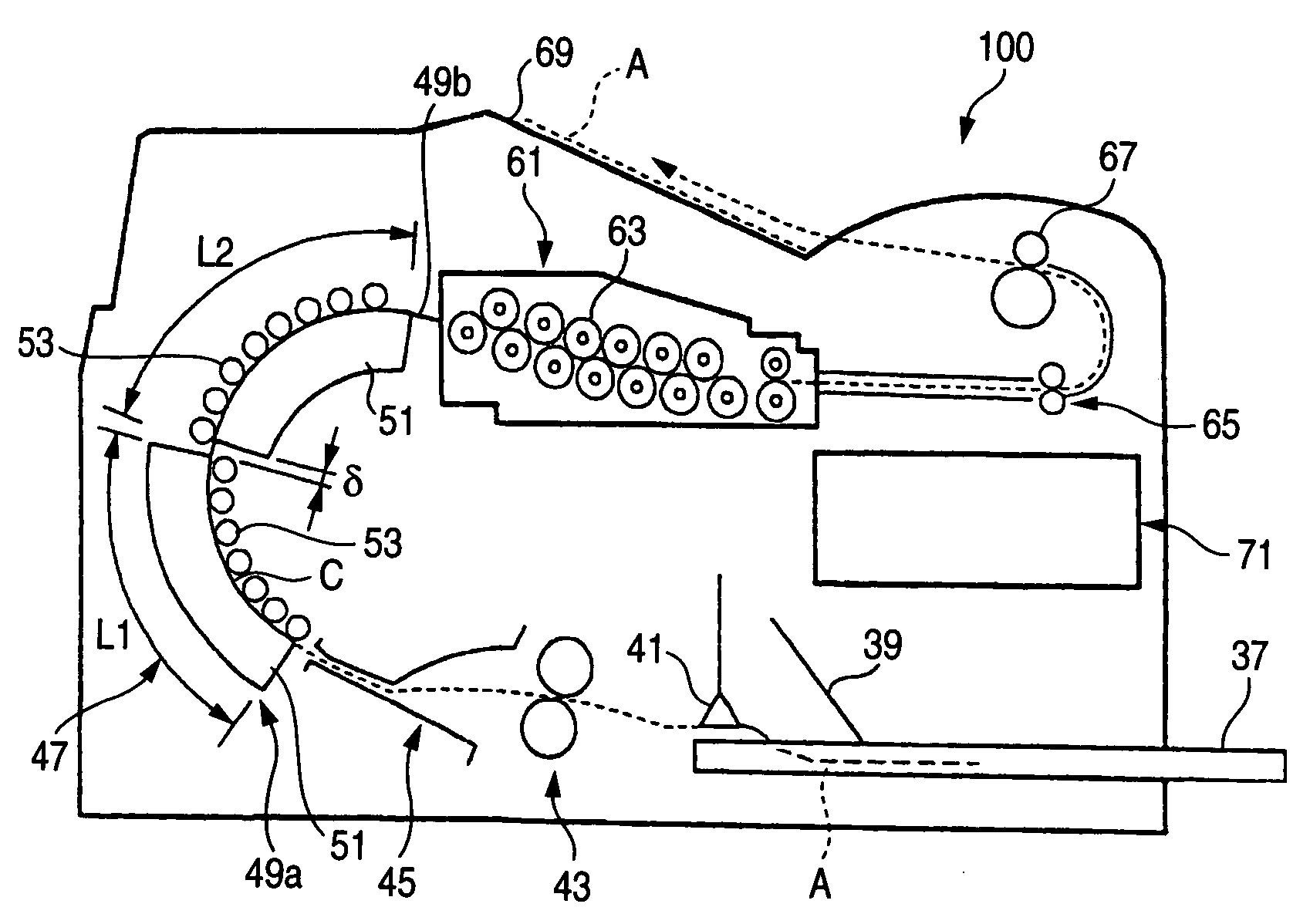
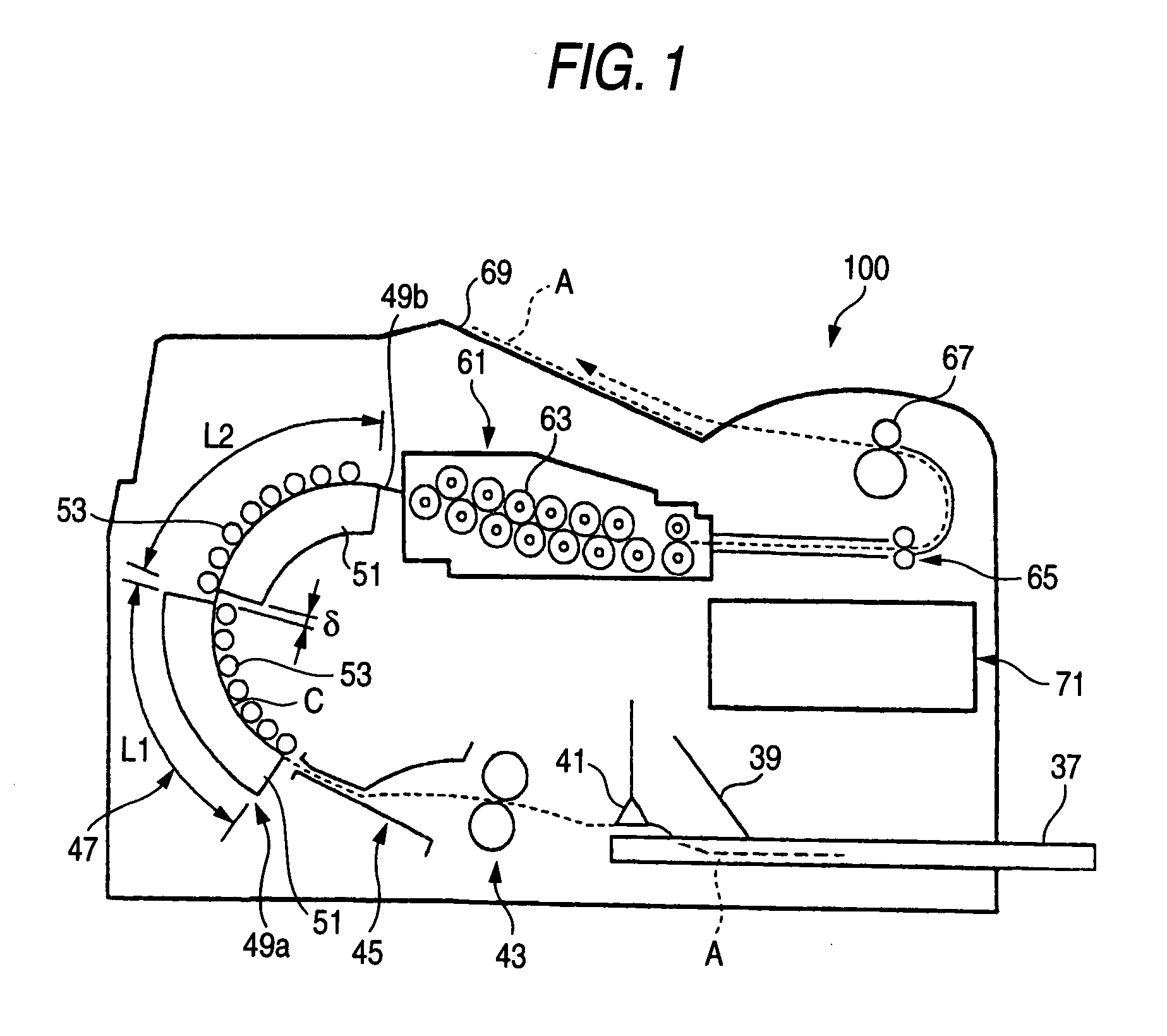
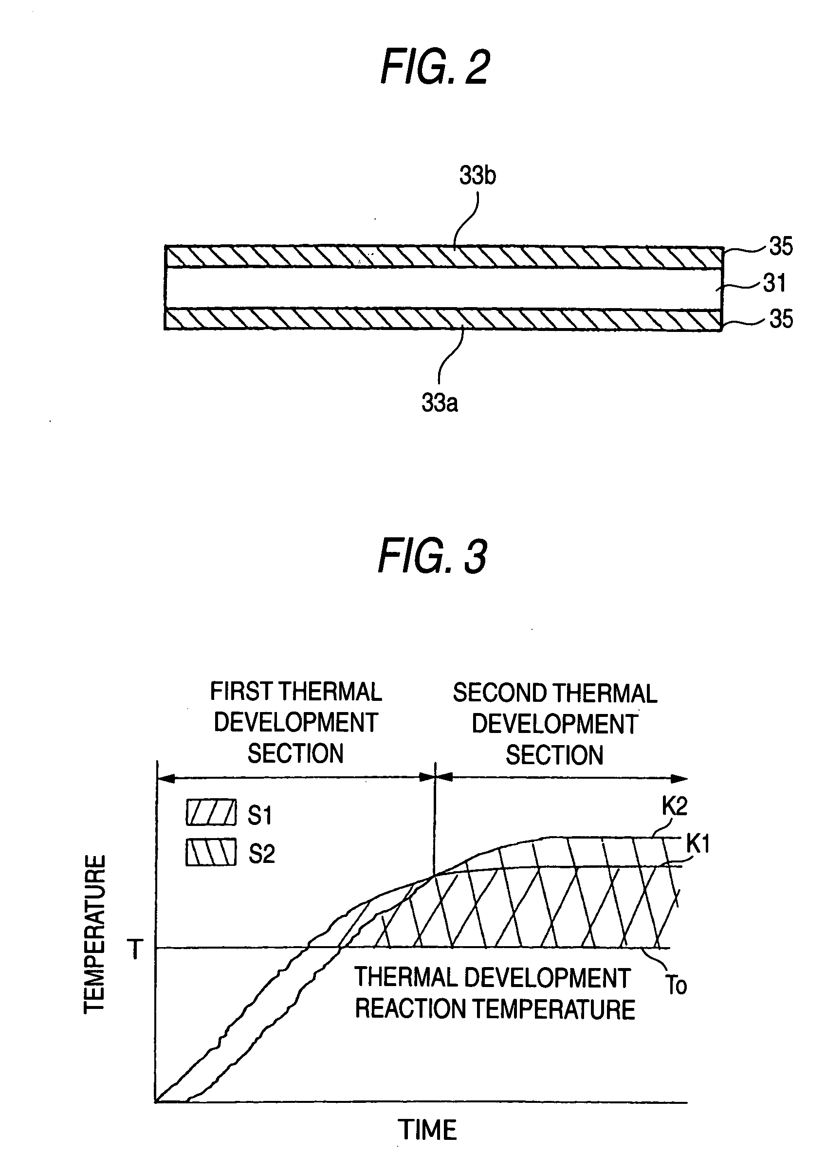
FIG. 1 is a block diagram showing an embodiment 1-1 of a thermal development apparatus according to the present invention; FIG. 2 is a cross-sectional view of a photosensitive photothermographic recording material; FIG. 3 is a descriptive view showing a correlation between the temperature and time of heating of front and back sides of the recording material which are alternately heated by means of the first and second heating units; and FIG. 4 is a block diagram of control means.

A thermal development apparatus 100 of the present embodiment heats a photosensitive photothermographic recording material (recording material) A, to thus render a latent image recorded on an image formation layer obvious. The recording material A employed by the thermal development apparatus 100 has a support 31 shown in FIG. 2. Image formation layers 35, 35 made of a photosensitive material are provided respectively on a first surface 33a which is one surface of the support 31 and a sec...

embodiment 1-2

(Embodiment 1-2)

FIG. 5 is a block diagram of an embodiment 1-2 showing the principal section of the thermal development apparatus having a drum and a press roller.

In a thermal development apparatus 200, each of first and second heating units 81a, 81b has a cylindrical drum 83 to be rotationally driven, and a plurality of press rollers 85 for pressing the recording material A against the circumferential surface of the drum 83. The heater serving as a heat source is incorporated in either the drum 83 or the press rollers 85. In the present embodiment, the heater serving as a heat source is incorporated in the drum 83.

The first and second heating units 81a, 81b are disposed in close proximity to each other. The drum 83 of the first heating unit 81a and the drum 83 of the second heating unit 81b are rotated in opposite directions. Accordingly, the first heating unit 81a and the second heating unit 81b constitute an S-shaped conveyance path C. Even in the thermal development apparatu...

embodiment 1-3

(Embodiment 1-3)

An embodiment 1-3 of the thermal development apparatus according to the present invention will now be described.

FIG. 6 is a block diagram showing the principal section of the thermal development apparatus having a support, an endless belt, and press rollers.

In a thermal development apparatus 300, each of first heating unit 91a and second heating unit 91b has a pipe-shaped support 93 having incorporated therein a heater H serving as a heat source, an endless belt 95 provided so as to enclose the support 93, and a press roller 97 for causing the endless belt 95 to follow and rotate by means of pressing the endless belt 95 against the support 93. In addition to being formed from a material having sufficient heat conduction such as resin, the endless belt 95 may be formed from a rubber heater or the like. So long as the amount of heat of respective heating unit is adjusted such that both surfaces of the recording material A are uniformly heated, the first heating uni...


PUM

PropertyMeasurementUnit
sphere-equivalent diameteraaaaaaaaaa
area-equivalent diameteraaaaaaaaaa

Abstract

In a thermal development method for generating a image from a latent image recorded on an image formation layer of a photosensitive photothermographic recording material, by means of heating the photosensitive photothermographic recording material, a first surface, which is one surface of the photosensitive photothermographic recording material A, and a second surface, which is the remaining surface of the same, are heated; and a total amount of heat applied to the second surface is controlled so as to fall within a range of 100±30 when a total amount of heat applied to the first surface is taken as 100 in connection with the respective total amounts of heat which are applied to the image formation layer from the first and second surfaces and equal to and higher than the development reaction temperature.

Description

BACKGROUND OF THE INVENTION 1. Field of the Invention The present invention relates to a thermal development method and apparatus for generating a image from a latent image recorded on an image formation layer of a photosensitive photothermographic recording material, by means of heating the photosensitive photothermographic recording material. 2. Description of the Related Art An image forming apparatus called, e.g., a medical imager, produces a print with a visible image from an image captured by a medical measuring machine, such as a CT or MRI device. The image forming apparatus employs a photosensitive photothermographic recording material (also called a “recording material”) produced by forming a photothermographic image formation layer on a support such as a PET film or the like. This photosensitive photothermographic recording material is exposed to a light beam which has been modulated in accordance with image data supplied from an image data supply source, such as an MR...

Claims


Application Information

Patent Timeline
Patent Type & Authority Applications(United States)
IPC IPC(8): G03C1/498G03C5/00G03D13/00
CPCB41J2/32B41J2/355G03C1/498G03C1/49881G03D13/002G03C2001/7425
Inventor OKADA, KOICHI
Owner FUJIFILM HLDG CORP
Why Eureka
Try Eureka