Voltage controlled oscillator, frequency synthesizer and communication apparatus

a frequency synthesizer and control technology, applied in the direction of pulse generators, pulse monitoring, pulse techniques, etc., can solve the problems of large circuitry, unsuitable for miniaturization, and adversely affect the spectrum of signals in transmitting and receiving

Inactive Publication Date: 2005-03-17
KK TOSHIBA
View PDF12 Cites 30 Cited by
  • Summary
  • Abstract
  • Description
  • Claims
  • Application Information

AI Technical Summary

Problems solved by technology

The phase noise of a VCO, through frequency conversion by a frequency mixer, adversely affects the spectrum of signals in transmitting and receiving.
In addition, the VCO requires an additional detection circuit for an oscillation signal and, therefore, is not suitable for miniaturization.
Therefore, the circuitry becomes large and phase noise reduction is difficult.
Therefore, there have been few disclosed frequency synthesizers with a VCO using a FBAR.

Method used


Image

  • Voltage controlled oscillator, frequency synthesizer and communication apparatus
  • Voltage controlled oscillator, frequency synthesizer and communication apparatus
  • Voltage controlled oscillator, frequency synthesizer and communication apparatus

Examples


first embodiment

(First Embodiment)

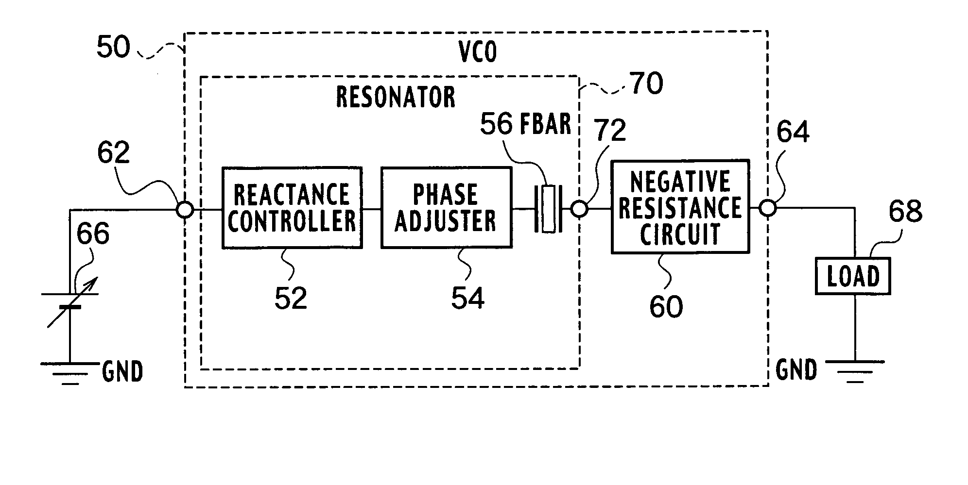
As shown in FIG. 1, a VCO 50 according to a first embodiment of the present invention includes a resonator 70 and a negative resistance circuit 60 connected to the resonator 70 at a connection node 72.

The resonator 70 includes a reactance controller 52 connected to an input node 62, a phase adjuster 54 connected in series to the reactance controller 52, and a FBAR 56 connected in series to the phase adjuster 54. A control voltage source 66, which is grounded, is connected to the input node 62. Moreover, an output node 64 is provided at the other end of the negative resistance circuit 60 which is connected to the resonator 70 at the connection node 72, and a load 68 is connected to the output node 64.

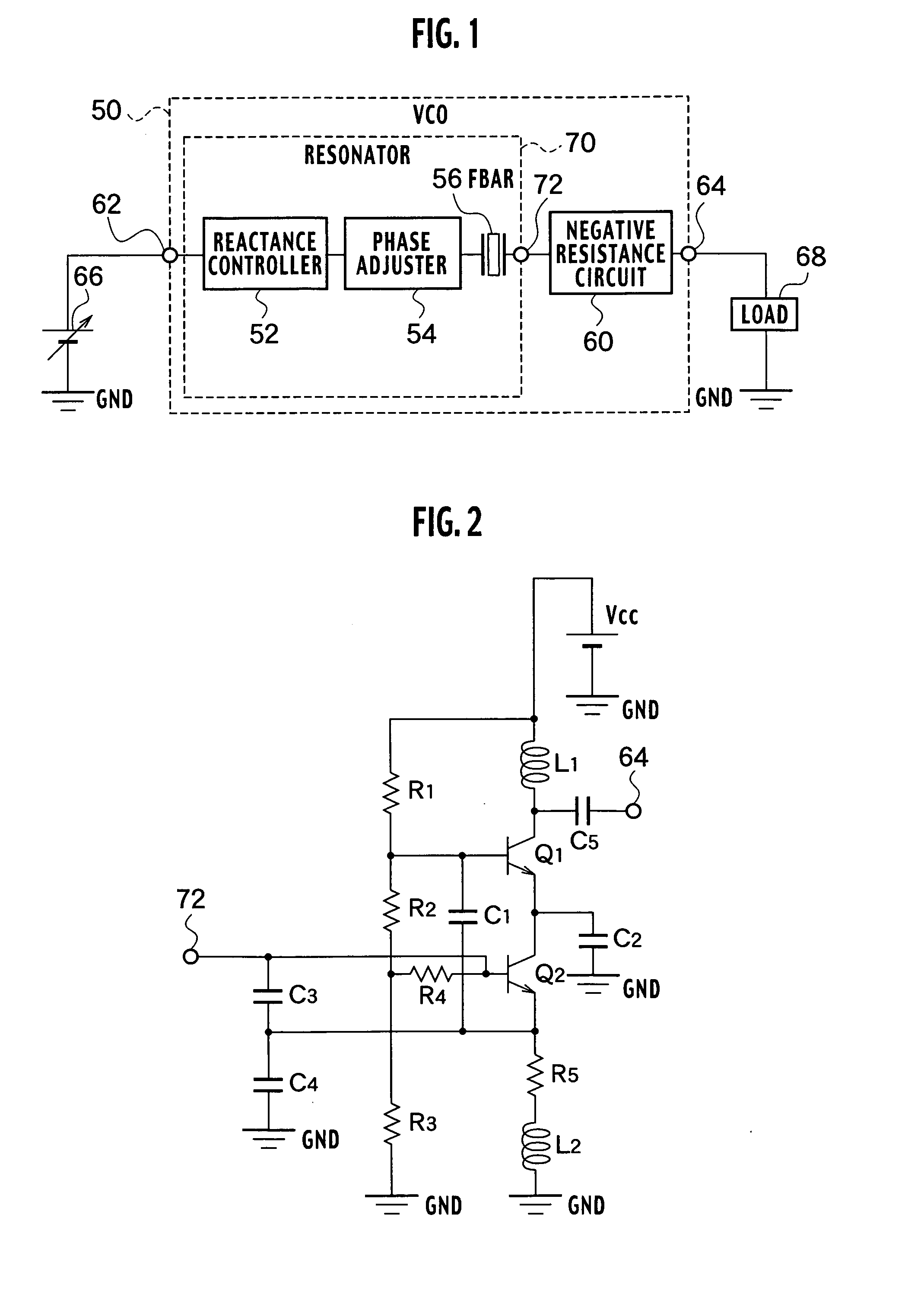
As shown in FIG. 2, the negative resistance circuit 60 includes an inductor L1 connected between a DC power supply Vcc which is grounded at a negative side, and a collector of a transistor Q1; a resistance R1 connected between the DC power supply Vcc and a base of ...

second embodiment

(Second Embodiment)

As shown in FIG. 27, a frequency synthesizer according to a second embodiment of the present invention includes a PLL circuit 99 which generates a high frequency oscillation signal SHF; first and second voltage comparators 96 and 98 which monitor a control voltage Vcontrol generated by the PLL circuit 99 so as to compare with first and second comparison potentials Vcomp1 and Vcomp2, respectively; and a control circuit 100 which generates any one of control signals SGC1 to SGC4 to the PLL circuit 99 based on an output signal VC1 or VC2 from the first or second voltage comparator 96 or 98.

The PLL circuit 99 includes first to fourth VCOs 51a to 51d having inputs connecting with each other, to which the control voltage Vcontrol for resonators in the respective VCOs is applied. The first to fourth VCOs 51a to 51d are connected to an output node 64 and to an input of a first frequency divider 82 via switches SW1 to SW4, respectively, which are connected to outputs of...


PUM


Abstract

A voltage controlled oscillator includes a resonator configured to resonate with an initial oscillation frequency during starting period of oscillation and a steady oscillation frequency during a steady state oscillation. The resonator includes a film bulk acoustic resonator having a series resonance frequency higher than the steady oscillation frequency. A negative resistance circuit configured to drive the resonator, has a positive increment for reactance in the steady state oscillation compared with reactance in the starting period.

Description

CROSS REFERENCE TO RELATED APPLICATIONS This application is based upon and claims the benefit of priority from prior Japanese Patent Application P2003-201199 filed on Jul. 24, 2003; the entire contents of which are incorporated by reference herein. BACKGROUND OF THE INVENTION 1. Field of the Invention The present invention relates to a voltage controlled oscillator using a film bulk acoustic resonator and, more particularly, to a voltage controlled oscillator having a variable oscillation frequency, a communication apparatus and a frequency synthesizer using the same. 2. Description of the Related Art In recent years, the market for a wireless communication system including a mobile phone and the like, has expanded, and at the same time, mobile communications services have been increasingly sophisticated. Moreover, it is expected that a local area network (LAN) system will rapidly become widespread in coming years. In these wireless communication systems, a radio frequency (RF)...

Claims


Application Information

Patent Timeline
Patent Type & Authority Applications(United States)
IPC IPC(8): H03B1/00H03B5/30H03B5/32H03K3/354H03H9/17H03L7/08H03L7/089H03L7/099H03L7/10H03L7/113H03L7/18H03L7/187H03L7/199H04B1/06H04B7/00
CPCH03B5/326H03B2200/0012H03B2201/0208H03B2201/025H03L7/0891H03L2207/06H03L7/10H03L7/113H03L7/18H03L7/199H03L7/099
Inventor ABE, KAZUHIDEMORIZUKA, MAYUMIOHARA, RYOICHISANO, KENYAYANASE, NAOKOYASUMOTO, TAKAAKISASAKI, TADAHIROITAYA, KAZUHIKOKAWAKUBO, TAKASHIYOSHIDA, HIROSHIFUJIMOTO, RYUICHIYAMAGUCHI, KEIICHIITOH, NOBUYUKIKOZU, TOORUOOKUBO, TAKESHI
Owner KK TOSHIBA
Why Eureka
Try Eureka