Subterranean treatment fluids and methods of treating subterranean formations

a technology of subterranean formations and treatment fluids, which is applied in the direction of transportation and packaging, chemistry apparatus and processes, and well accessories, etc., can solve the problems of acid loss into the formation, damage to the producing formation, and equipment premature failure, so as to reduce the loss of fluid to the formation through the self-degrading filter cake

Active Publication Date: 2005-03-17
HALLIBURTON ENERGY SERVICES INC
View PDF99 Cites 132 Cited by
  • Summary
  • Abstract
  • Description
  • Claims
  • Application Information

AI Technical Summary

Benefits of technology

An example of a method of the present invention comprises the steps of: placing a well drill-in and servicing fluid in a subterranean formation, the well drill-in and servicing fluid comprising a viscosifier, a fluid loss control additive, and

Problems solved by technology

This method is problematic, however, because the strong acid often corrodes metallic surfaces and completion equipment such as sand control screens, thereby causing such equipment to prematurely fail.
Further, the acid may damage the producing formation.
Additionally, the acid may cause the bridging agent to dissolve too quickly, resulting in the acid being lost into the formation,

Method used


Image

  • Subterranean treatment fluids and methods of treating subterranean formations
  • Subterranean treatment fluids and methods of treating subterranean formations
  • Subterranean treatment fluids and methods of treating subterranean formations

Examples


example 1

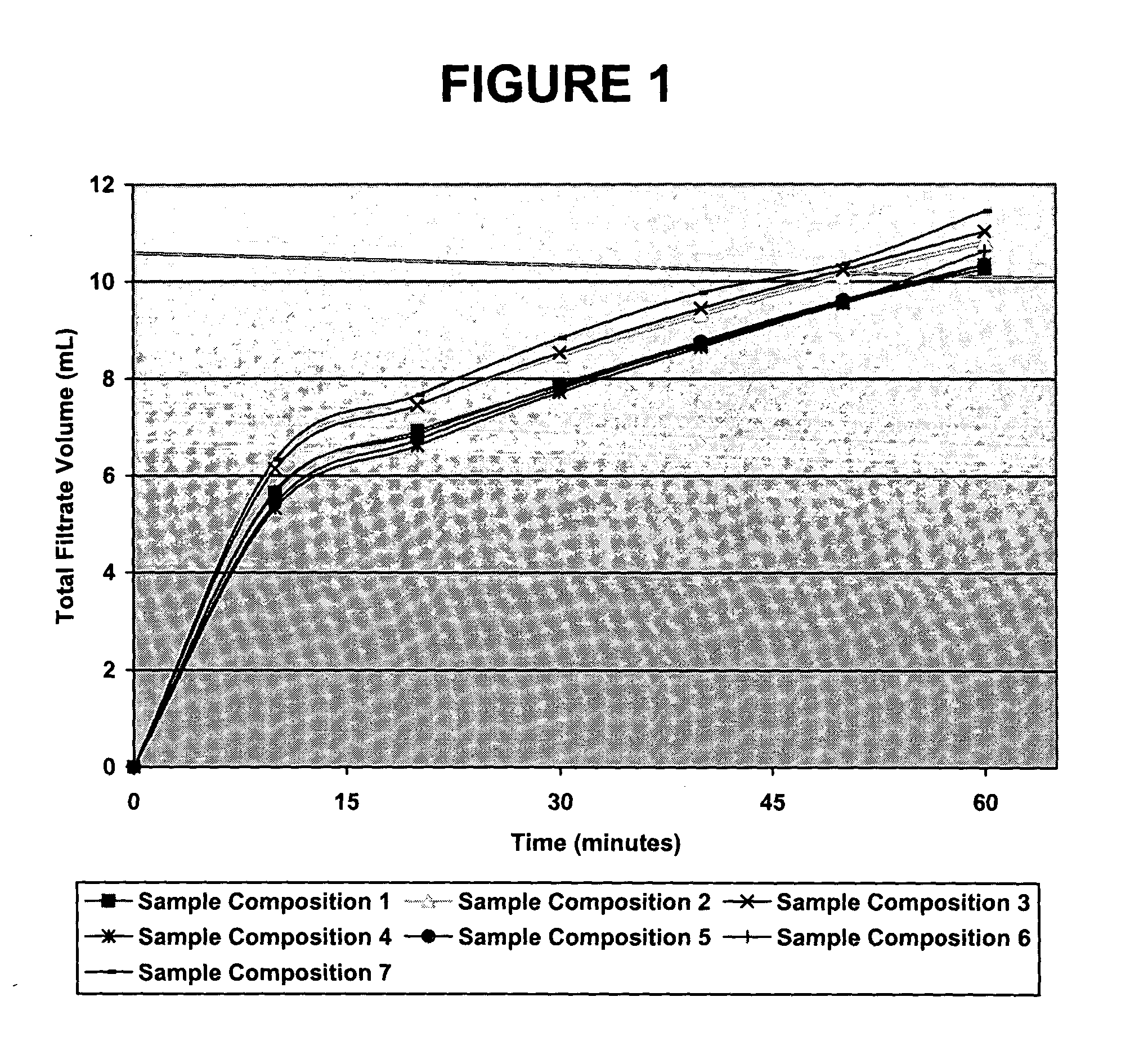
A dynamic filtration test was conducted, in a Fann Model 90B dynamic filtration tester, in which seven embodiments of filter cakes of the present invention were constructed. For each of the seven embodiments, a sample composition was formulated comprising 336 mL of a 10% aqueous solution of sodium chloride by weight, to which 0.85 grams of clarified liquid xanthan biopolymer, 7.4 grams of a non-ionic starch derivative, 20 grams of powdered polylactic acid, and 30 grams of calcium carbonate were added. This sample composition was then hot rolled for 16 hours at 150° F.

The dynamic filtration test comprised constructing filter cakes on the inner diameter of a synthetic core comprising “ALOXIT™” having a 35 micron pore throat size. The filter cakes were constructed by continuously shearing each sample composition inside the core for an hour while applying a differential pressure of 500 psid, during which time the filter cake formed on the core's inner diameter. The porous nature of t...

example 2

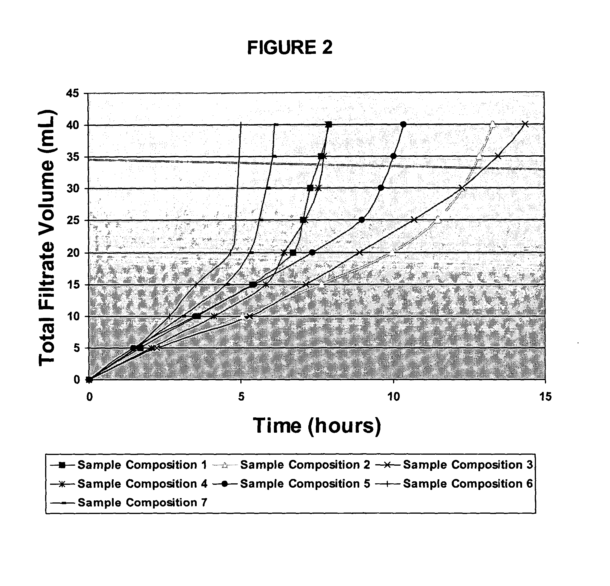
The seven sample filter cakes prepared in Example 1 were then each subjected to a break test, in which a 10% aqueous solution of sodium chloride by weight was injected into the core at 50 psi differential pressure. Break tests for Sample Compositions 1, 2, 4, and 6 were conducted at 200° F., while break tests for Sample Compositions 3, 5 and 7 were performed at 180° F. As the sodium chloride solution began to break down each filter cake, the amount of filtrate (e.g., the amount of broken filter cake) was collected and measured. The break test continued until such time as the maximum filtrate volume (50 mL) of a particular sample was collected in the Model 90B dynamic filtration tester. The results are illustrated in Table 2 below and in FIG. 2.

TABLE 2Time (hrs)TotalSampleSampleSampleSampleSampleSampleSampleFiltrateCompositionCompositionCompositionCompositionCompositionCompositionCompositionVolume (mL)12345670000000051.712.252.252.071.451.511.59103.595.065.284.113.492.663.07155.39...


PUM

PropertyMeasurementUnit
Fractionaaaaaaaaaa
Fractionaaaaaaaaaa
Fractionaaaaaaaaaa

Abstract

The present invention relates to bridging agents for use in subterranean formations, to well drill-in and servicing fluids comprising such bridging agents, and to methods of using such bridging agents and well drill-in and servicing fluids in subterranean drilling operations. An example of a well drill-in and servicing fluid of the present invention comprises a viscosified fluid, a fluid loss control additive, and a bridging agent comprising a degradable material.

Description

BACKGROUND OF THE INVENTION 1. Field of the Invention The present invention relates to bridging agents for use in subterranean formations, to well drill-in and servicing fluids comprising such bridging agents, and to methods of using such bridging agents and well drill-in and servicing fluids in subterranean drilling operations. 2. Description of Related Art Often, once drilling of a well bore in a subterranean formation has been initiated, an operator will employ a fluid referred to as a “well drill-in and servicing fluid.” As referred to herein, the term “well drill-in and servicing fluid” will be understood to mean a fluid placed in a subterranean formation from which production has been, is being, or may be cultivated. For example, an operator may begin drilling a subterranean borehole using a drilling fluid, cease drilling at a depth just above that of a productive formation, circulate a sufficient quantity of a well drill-in and servicing fluid through the bore hole to com...

Claims


Application Information

Patent Timeline
IPC IPC(8): C09K8/03C09K8/06C09K8/504C09K8/508C09K8/52
CPCC09K8/03C09K8/06C09K8/5045Y10T428/2982C09K8/52C09K2208/18C09K8/508
Inventor TODD, BRADLEY L.MUNOZ, TRINIDAD JR.
Owner HALLIBURTON ENERGY SERVICES INC
Why Eureka
Try Eureka