
Method and apparatus for cooling devices that in use generate unwanted heat

Inactive Publication Date: 2005-03-24
UNIV OF WASHINGTON
View PDF13 Cites 60 Cited by
  • Summary
  • Abstract
  • Description
  • Claims
  • Application Information

AI Technical Summary

Benefits of technology

[0007] In accordance with another embodiment of the invention, the enclosed space has a plurality of compartments and each compartment contains at least one device that in use generates heat. Each compartment has an ambient air inlet, an outlet and an air mover for moving ambient air through the compartment from the inlet of the compartment to the outlet of the compartment. By way of example, the air mover can be a fan or pump positioned in the compartment and adapted for moving the air from the inlet to the outlet of the compartment. In this embodiment, the air cooler is smaller than the entire enclosed space. It has an inlet, an inner space, an outlet and a device in the inner space that is adapted for removing heat from the ambient air as the ambient air passes through the inner space from the inlet to the outlet. This cooler is adapted to be positioned with its outlet in register with the ambient air inlet for at least one compartment of the enclosed space. The ambient air that is moved through the at least one compartment of the enclosed space is ambient air that has been cooled by the cooler. The coolers used with compartments in which substantial heat is generated can be provided with a greater cooling capacity than the coolers associated with other compartments in which less heat is generated. By placing the cooler immediately in front of the compartment which requires the most cooling, “hot spots” in the room are avoided. Also, extreme density cooling (about 20 about 50 Kw. per rack or compartment, or more) may be efficiently and effectively performed.

Problems solved by technology

These systems have been found to be inadequate when the heat density is above about 8 Kw.
None of the existing systems are able to effectively operate in an environment in which the heat density is between about 20 to about 40 Kw.
The known systems fail when the power level raises to about 400 watts per square foot, or when the cooling requirements vary substantially in a given space.
When airflow in a single rack approaches about 3,000 cubic feet per minute, and an aisle of about 20 racks approaches 52,000 cubic feet per minute, the conventional systems cannot handle the airflow in a computer room of conventional size.
The use of larger rooms is expensive and they are still subject to the airflow problems that are created.
These problems include the creation of “hot spots” which are regions in the room that are not sufficiently cooled and in which the devices that generate the heat are adversely affected by the heat.

Method used


Image

  • Method and apparatus for cooling devices that in use generate unwanted heat
  • Method and apparatus for cooling devices that in use generate unwanted heat
  • Method and apparatus for cooling devices that in use generate unwanted heat

Examples


Embodiment Construction

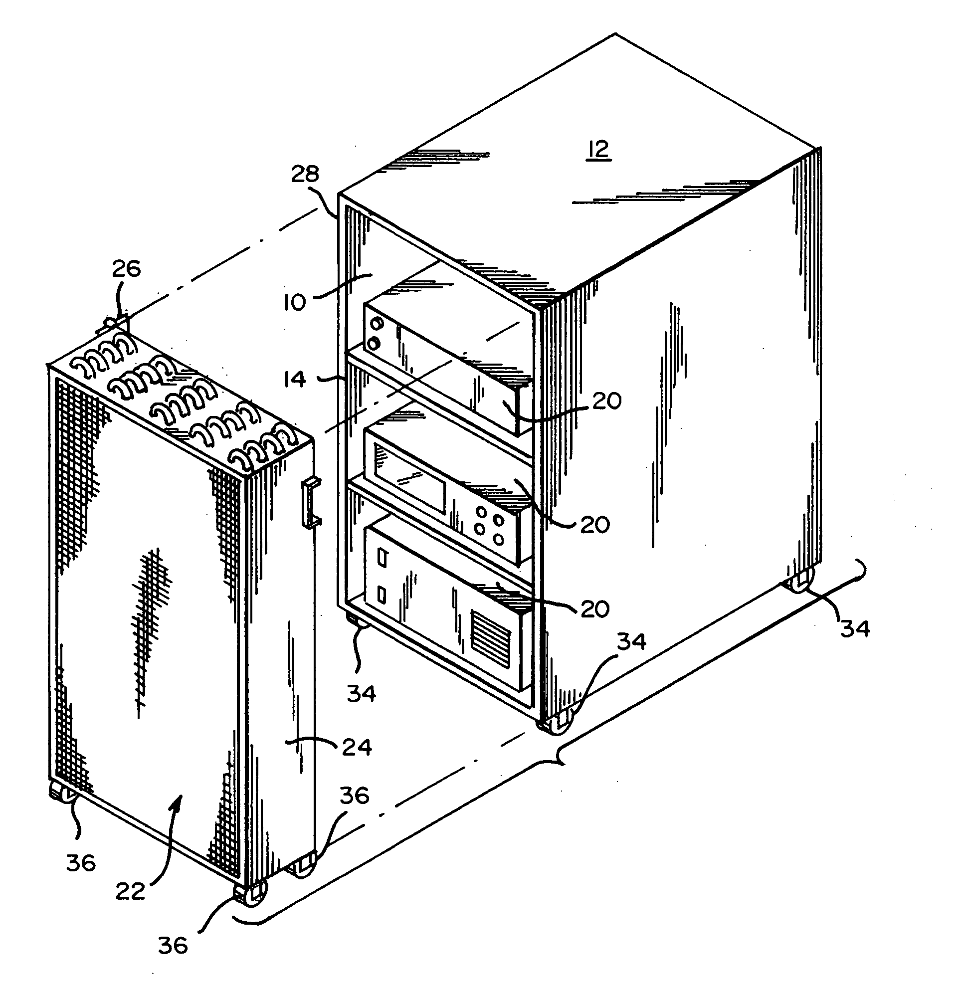
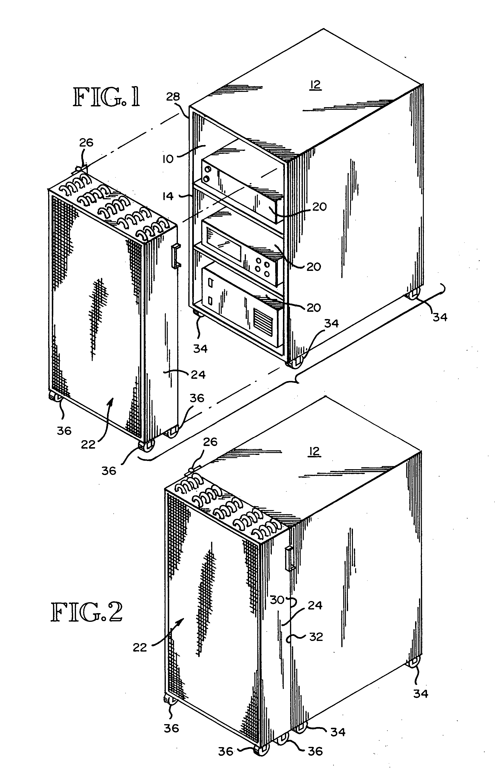
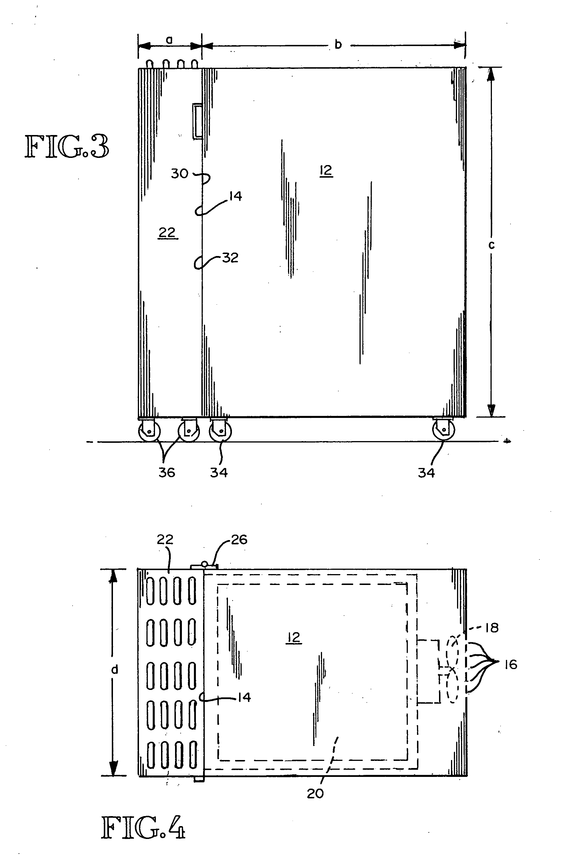
[0018]FIGS. 1-4 show an enclosed space 10 that is within a housing or cabinet 12. The enclosed space 10 and the housing 12 have an inlet 14, an outlet 16 and an air mover 18 for moving ambient air through the space 10 from the inlet 14 to the outlet 16. The enclosed space 10 also includes at least one device 20 that in use generates heat. In FIG. 1, the housing or cabinet 12 may be a standard computer housing or may be a rack of computer components, or similar equipment. At least some of the computer components generate heat when they are in use.

[0019] A cooler 22 is provided for cooling ambient air at a location immediately forwardly of the inlet 14. Any device that can cool a fluid can be used forwardly of the inlet 14. In the embodiments shown by FIGS. 1-4, the cooler 22 is located within a housing 24 that is connectable to the housing 12, in the manner shown by FIGS. 2-4. By way of example, one or more hinges 26 may be provided along one rear corner boundary of the cooler 22, f...


PUM


Abstract

A cooler comprising coils and passageways defined by and between the coils through which ambient air moves, from the inlet of the cooler to the outlet of the cooler, is positioned with its outlet in register with an ambient air inlet for an enclosed space. A device that in use generates heat is positioned within the enclosed space. The enclosed space includes an ambient air inlet and an outlet through which ambient air from the ambient air inlet to the outlet. The cooler is used to cool the ambient air that is immediately forwardly of the ambient air inlet for the enclosed space. An air mover in the enclosed space, or thermal flow, is used for moving the cooled ambient air into the ambient air inlet, through the enclosed space, and out from the outlet of the enclosed space.

Description

RELATED APPLICATION [0001] This application claims benefit of the filing date of Provisional Application No. 60 / 501,906, filed Sep. 10, 2003, and entitled Cooling System For Electronic Equipment.TECHNICAL FIELD [0002] This invention relates to devices, such as computers, that in use generate unwanted heat making it necessary to cool the devices. More particularly, it relates to a method and apparatus for providing cool ambient air directly in front of the devices that need to be cooled. BACKGROUND OF THE INVENTION [0003] Computers are sometimes cooled by cooling the air in the room in which the computers are located. When air is used as the cooling medium, variations in airflow occur, particularly when the heat density rises in a region of the equipment room, or when the absolute heat load approaches the maximum load that the air can handle. In an effort to solve resulting problems, systems have been made in which the devices that heat up are placed inside of a closure and the air i...

Claims


Application Information

Patent Timeline
IPC IPC(8): F25D11/00G06F1/18G06F1/20H05K7/20
CPCF25D11/003F25D2400/38H05K7/20827G06F1/20G06F1/183
Inventor BOND, RICHARD C.
Owner UNIV OF WASHINGTON
Features
  • Generate Ideas
  • Intellectual Property
  • Life Sciences
  • Materials
  • Tech Scout
  • Unparalleled Data Quality
  • Higher Quality Content
  • 60% Fewer Hallucinations
Learn More