
Valve drive system for four-stroke engine

a four-stroke engine and valve drive technology, applied in the direction of machines/engines, mechanical equipment, cylinders, etc., can solve the problems of complicated rocker arms, increased cost, heavy and larger rocker arms, etc., and achieve the effect of facilitating the adjustment work

Active Publication Date: 2005-03-24
YAMAHA MOTOR CO LTD
View PDF6 Cites 17 Cited by
  • Summary
  • Abstract
  • Description
  • Claims
  • Application Information

AI Technical Summary

Benefits of technology

[0009] In the four-stroke engine disclosed in Japanese Patent Application No. 2001-193426, a rocker arm is provided with an adjusting screw to be in abutment against the top end of the valve stem. Therefore, turning the adjusting screw allows adjustment of the tappet clearance, facilitating the adjusting work.
[0012] In the case of this four-stroke engine, the rocker arm is formed, at one end, with a slipper, and the slipper is in contact with intake and exhaust cams on the camshaft for sliding movement. However, the slipper type rocker arm has a large frictional resistance produced in the contact portions with the intake and exhaust cams compared with a roller type rocker arm, raising a problem of early wear of the slipper and the intake and exhaust cams particularly when proper lubrication control is neglected.
[0014] In view of the foregoing, an object of this invention is to provide a valve drive system for a four-stroke engine capable of suppressing the frictional resistance produced in the contact portions of rocker arms with valve drive cams to a small value and facilitating replacement work of tappet-clearance adjusting shims.
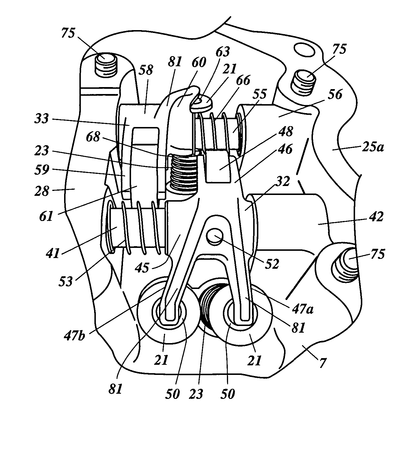
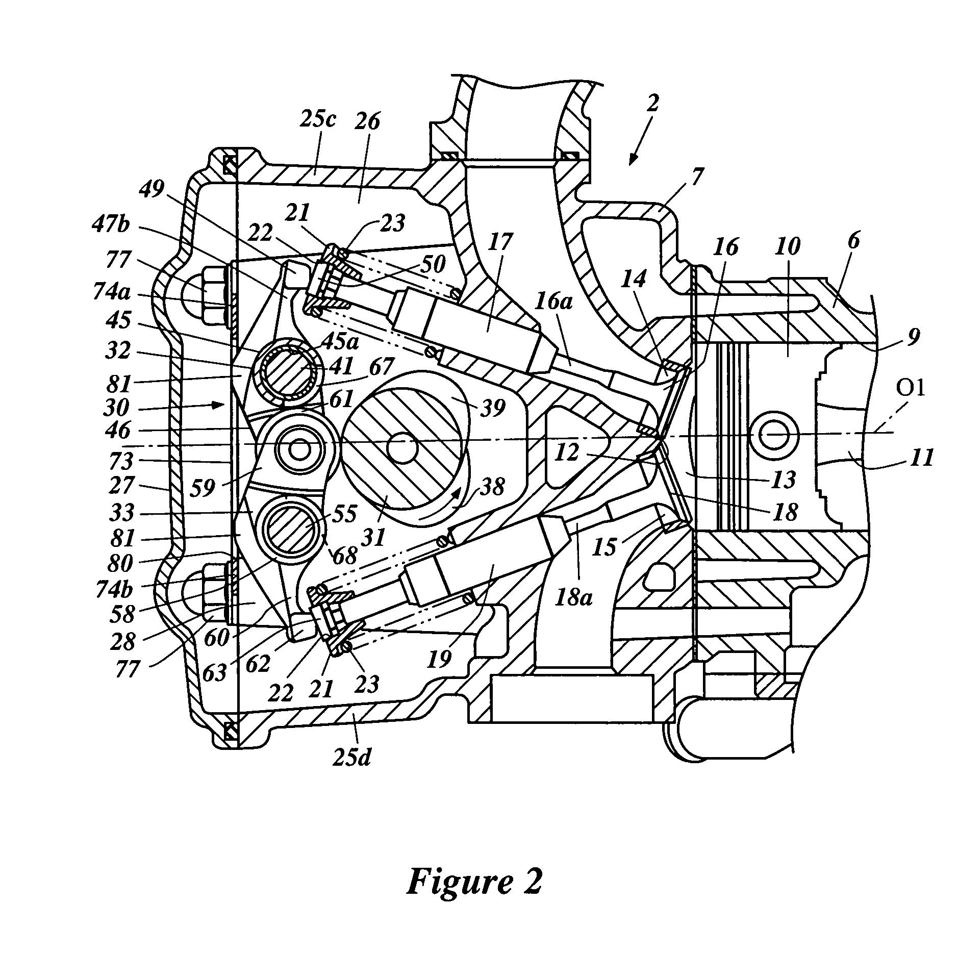
[0016] Thus, the frictional resistance produced in the contact portions of rocker arms with cams on a camshaft can be reduced. Wear of cams can also be suppressed and the reduction in friction loss enables increased engine performance. In addition, adjustment of tappet clearance can be performed by selecting a shim of proper thickness and fitting the shim between the pushing portion of the rocker arm and the valve stem. Therefore, the rocker arm need not be provided with an additional adjusting screw and a lock nut, enabling size reduction and weight saving of the rocker arm.
[0017] In some embodiments, where the rocker arms can be dislocated to the sides of the valve stems, it is not necessary, at the time of replacement of shims, to remove the camshaft from the cylinder head, nor is it necessary to hold the valves are in the highest lift position with special tools. Thus, replacement work of shims can be performed easily, providing better working efficiency.

Problems solved by technology

However, according to Japanese Patent Application No. 2001-193426, since an adjusting screw and a lock nut for securing the screw are mounted on the rocker arm, the construction of the rocker arm is complicated, resulting in a higher cost.
In addition, the rocker arm is heavier and larger, which is a factor limiting engine speed.
However, the slipper type rocker arm has a large frictional resistance produced in the contact portions with the intake and exhaust cams compared with a roller type rocker arm, raising a problem of early wear of the slipper and the intake and exhaust cams particularly when proper lubrication control is neglected.

Method used


Image

  • Valve drive system for four-stroke engine
  • Valve drive system for four-stroke engine
  • Valve drive system for four-stroke engine

Examples


Embodiment Construction

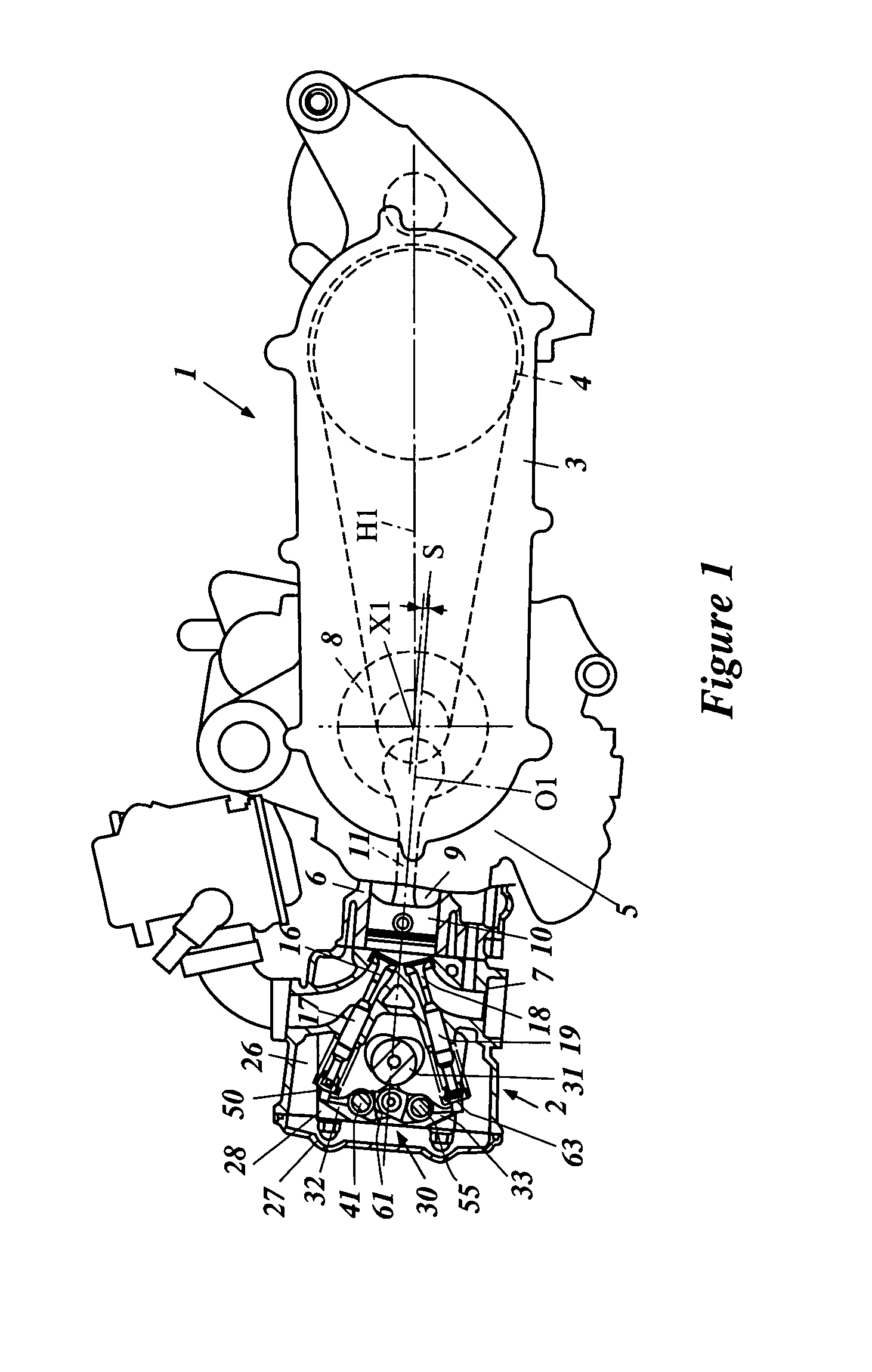
[0030] With reference to the figures, preferred embodiments are described below in detail. FIG. 1 shows an example of an engine for a small of straddle-type vehicle with which embodiments of the present inventions can be used.

[0031] For example, the illustrated embodiment is a swing-type engine unit 1 for use, for example, but without limitation, with a scooter-type motorcycle. The engine unit 1 can include a water-cooled, four-stroke, single-cylinder engine 2, and a transmission case 3 acting also as a swing arm.

[0032] The transmission case 3 extends from the four-stroke engine 2 toward the drive wheel. For example, but without limitation, the transmission case 3 can extend toward the rear wheel (not shown) of a scooter-type motorcycle. The transmission case 3 can contain a V-belt type automatic transmission 4. A rear wheel (not shown) can be supported at the rear end of the transmission case 3, as noted above, and driven by the V-belt type automatic transmission 4.

[0033] The fo...


PUM


Abstract

A valve drive system capable of reducing the friction resistance of rocker arms and facilitating replacement work of tappet-clearance adjusting shims. The valve drive system can comprise a rocker arm that is slidable between a first position at which the pushing portion engages the shim and a second position at which the pushing portion is disengaged from the shim, and held in the first position through a spring.

Description

PRIORITY INFORMATION [0001] The present application is based on and claims priority under 35 U.S.C. § 119 to Japanese Patent Application No. 2003-330046, filed on Sep. 22, 2003, the entire contents of which are expressly incorporated by reference herein. BACKGROUND OF THE INVENTIONS [0002] 1. Field of the Inventions [0003] The present inventions generally relate to a valve drive system for a four-stroke engine in which rollers in rolling contact with an intake cam and an exhaust cam are incorporated in rocker arms for opening and closing an intake and an exhaust valve. [0004] 2. Description of the Related Art [0005] The so-called single over-head cam “SOHC” type four-stroke engine in which an intake valve and an exhaust valve are opened or closed through one camshaft, typically includes an intake rocker arm for transmitting the movement of an intake cam to the intake valve and an exhaust rocker arm for transmitting the movement of an exhaust cam to the exhaust valve. [0006] The inta...

Claims


Application Information

Patent Timeline
Patent Type & Authority Applications(United States)
IPC IPC(8): F01L1/12F01L1/18F01L1/20F01L1/26F01L1/46F02F1/24
CPCF01L1/022F01L1/181Y10T74/2107F01L1/26F01L1/46F01L1/205
Inventor NAKAHIRA, YASUYUKI
Owner YAMAHA MOTOR CO LTD
Learn More