Suspension board with circuit and procuding method thereof

a suspension board and circuit technology, applied in the direction of conductive pattern formation, printed element electric connection formation, maintaining head carrier alignment, etc., to achieve the effect of reducing the number of processes, and preventing the occurrence of corrosion or defects of the conductor layer effectively

Active Publication Date: 2005-03-24
NITTO DENKO CORP
View PDF3 Cites 82 Cited by
  • Summary
  • Abstract
  • Description
  • Claims
  • Application Information

AI Technical Summary

Benefits of technology

[0013] According to the suspension board with circuit of the present invention thus produced, before the process of forming the first opening, the metal support layer is electrically conductive with the conductor layer via the thin metal film. Hence, the metal support layer can be used as the lead portion of the electrolysis plating for forming the terminal portion in this process. Also, in the suspension board with circuit thus produced, the conductor layer is covered with the thin metal film without being exposed directly from the second opening and thus is prevented from being exposed to outside. This can prevent occurrence of corrosion or defects of the conductor layer effectively.
[0014] Also, according to the method of producing a suspension board with circuit of the present invention, before the process of formi

Problems solved by technology

However, in the method outlined above, since the conductor layer remains exposed to outside at the end thereof as it is after the removal of t

Method used


Image

  • Suspension board with circuit and procuding method thereof
  • Suspension board with circuit and procuding method thereof
  • Suspension board with circuit and procuding method thereof

Examples


example

[0085] While in the following, the present invention will be described in further detail with reference to Example, the present invention is not limited to Example.

Production of Suspension Board with Circuit

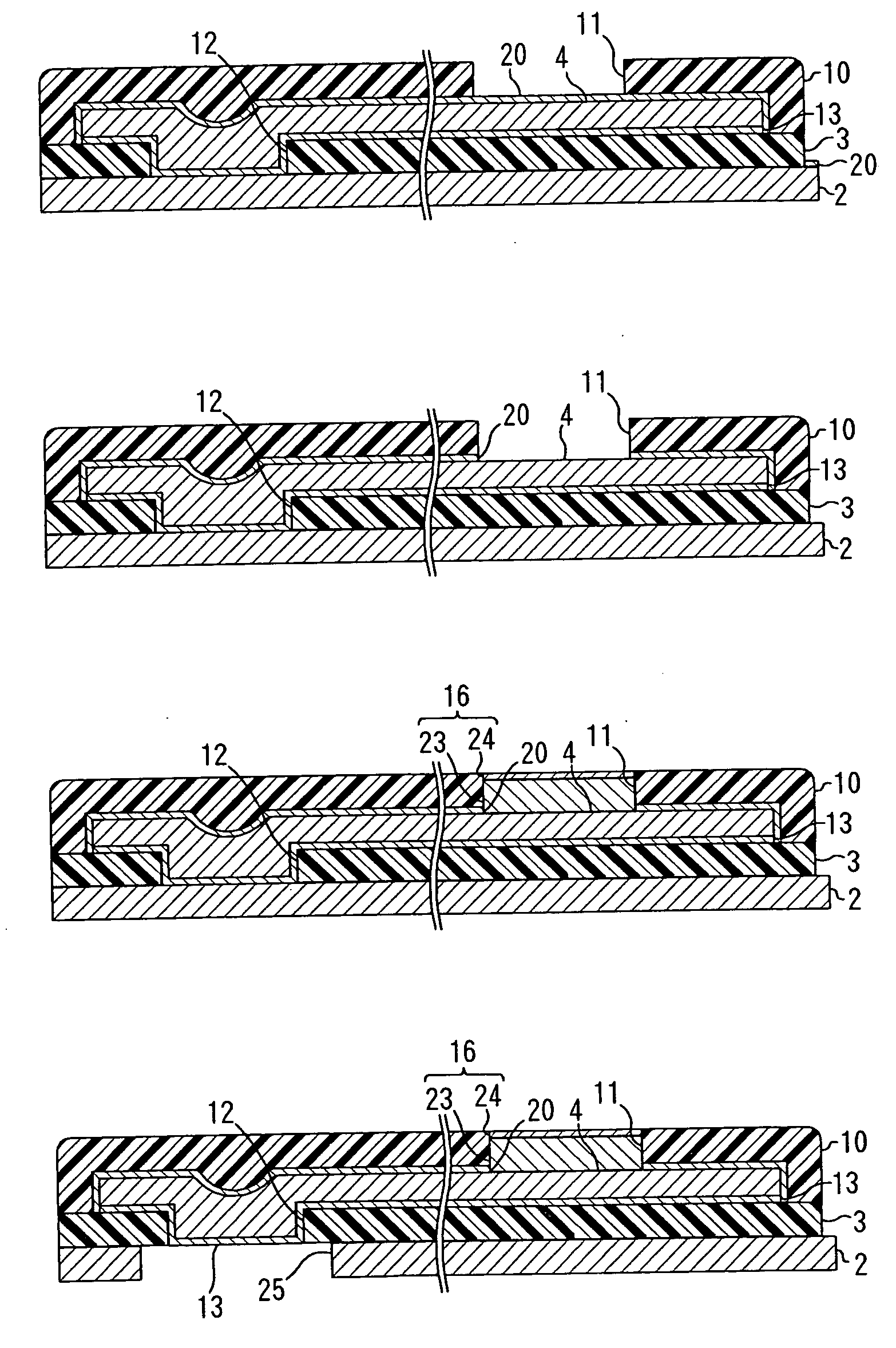
[0086] Liquid solution of polyamic acid resin was applied on the stainless foil having thickness of 25 μm and then heated at 130° C. to thereby form a coating of the polyamic acid resin. Sequentially, the coating was exposed to light (405 nm, 1,500 mJ / cm2) through the photo mask. The exposed part was heated to 180° C. and then developed using alkaline developer, whereby the coating was formed in the specific pattern including the second opening with the negative image.

[0087] Sequentially, the patterned coating of the polyamic acid resin was heated at 350° C. to be cured (imidized), whereby the insulating base layer of polyimide resin of thickness of 15 μm was formed in the specific pattern including the second opening. The second opening was formed in a circular shape having a...


PUM


Abstract

A producing method of a suspension board with circuit that can permit a terminal portion to be formed by electrolysis plating without exposing a conductor layer to outside and also can reduce the number of processes, and the suspension board with circuit produced by the same producing method. After an insulating base layer 3 is formed on a suspension board 2 in a specific pattern in which a second opening 12 is formed, a thin metal film 13 is formed on an entire surface of the insulating base layer 3 and on a surface of the suspension board 2 including the second opening 12 exposed from the insulating base layer 3.Then, a conductor layer 4 is formed in the form of a wired circuit pattern on the thin metal film 13. Thereafter, the insulating cover layer 10 is formed in such a manner that a pad opening 11 is formed in the insulating cover layer 10 and then a pad portion 16 is formed in the pad opening 11 using the suspension board 2 as a lead portion of the electrolysis plating. Thereafter, a first opening 25 larger than the second opening 12 is formed in the suspension board 2 at a portion thereof corresponding to the second opening 12.

Description

BACKGROUND OF THE INVENTION [0001] 1. Field of the Invention [0002] The present invention relates to a suspension board with circuit and to a producing method thereof. More particularly, the present invention relates to a suspension board with circuit mounting thereon a magnetic head of a hard disc drive and to a producing method thereof. [0003] 2. Description of the Prior Art [0004] A suspension board with circuit mounts thereon a magnetic head of a hard disk drive and supports the magnetic head, with a minute interval between the magnetic head and a magnetic disk held against an airflow generated when the magnetic head and the magnetic disk run relative to each other. [0005] A terminal portion of this suspension board with circuit is usually formed by carrying out electrolysis nickel plating and electrolysis gold plating sequentially. When the terminal portion is formed in this plating process, part of a conductor layer of the suspension board with circuit is used as a lead portio...

Claims


Application Information

Patent Timeline
IPC IPC(8): H05K1/05G11B5/60H05K1/11H05K3/06H05K3/10H05K3/24H05K3/28H05K3/38H05K3/40H05K3/44
CPCH05K1/056H05K3/06H05K3/108H05K3/243H05K3/244H05K3/28H05K2203/0723H05K3/388H05K3/4007H05K3/44H05K2201/0969H05K2203/0323H05K3/384
Inventor AONUMA, HIDENORIOHWAKI, YASUHITO
Owner NITTO DENKO CORP
Why Eureka
Try Eureka