Method and apparatus for forming construction panels and structures

a technology for building panels and structures, applied in the field of formwork, can solve the problems of poor finish of construction panels or structures cast in such formwork, inability to use, and inability to meet the needs of construction workers, and achieve the effect of low cost and simple us

Inactive Publication Date: 2005-03-24
NICOLO ASSUNTA
View PDF43 Cites 20 Cited by
  • Summary
  • Abstract
  • Description
  • Claims
  • Application Information

AI Technical Summary

Benefits of technology

[0019] It is the object of the present invention to address in part or in total one or more of the problems of using the Tiltfo

Problems solved by technology

These types of timbers are prone to weathering and there is often considerable variation between timbers.
A construction panel or structure cast in such formwork will normally have a poor finish and cannot be used where there are small dimensional tolerances.
Pre-cast panels suffer from the limitation that they must be transported to the work-site for erection or use.
Cranes and significant labour are required to place the panels.
This significantly adds to the cost of using pre-cast panels or structures and limits the maximum size of the panel.
Both of the described on-site and pre-casting methods require skilled individuals to create the moulds and are very labour intensive.
This significantly adds to the cost of either of these methods.
One of the main problems with this system is the need to use buttress frames as they introduce a number of limitations and requirements.
The buttress frames are heavy and cumbersome and are typically delivered to building sites in stillages.
This means that a large amount of space is used during

Method used


Image

  • Method and apparatus for forming construction panels and structures
  • Method and apparatus for forming construction panels and structures
  • Method and apparatus for forming construction panels and structures

Examples


Embodiment Construction

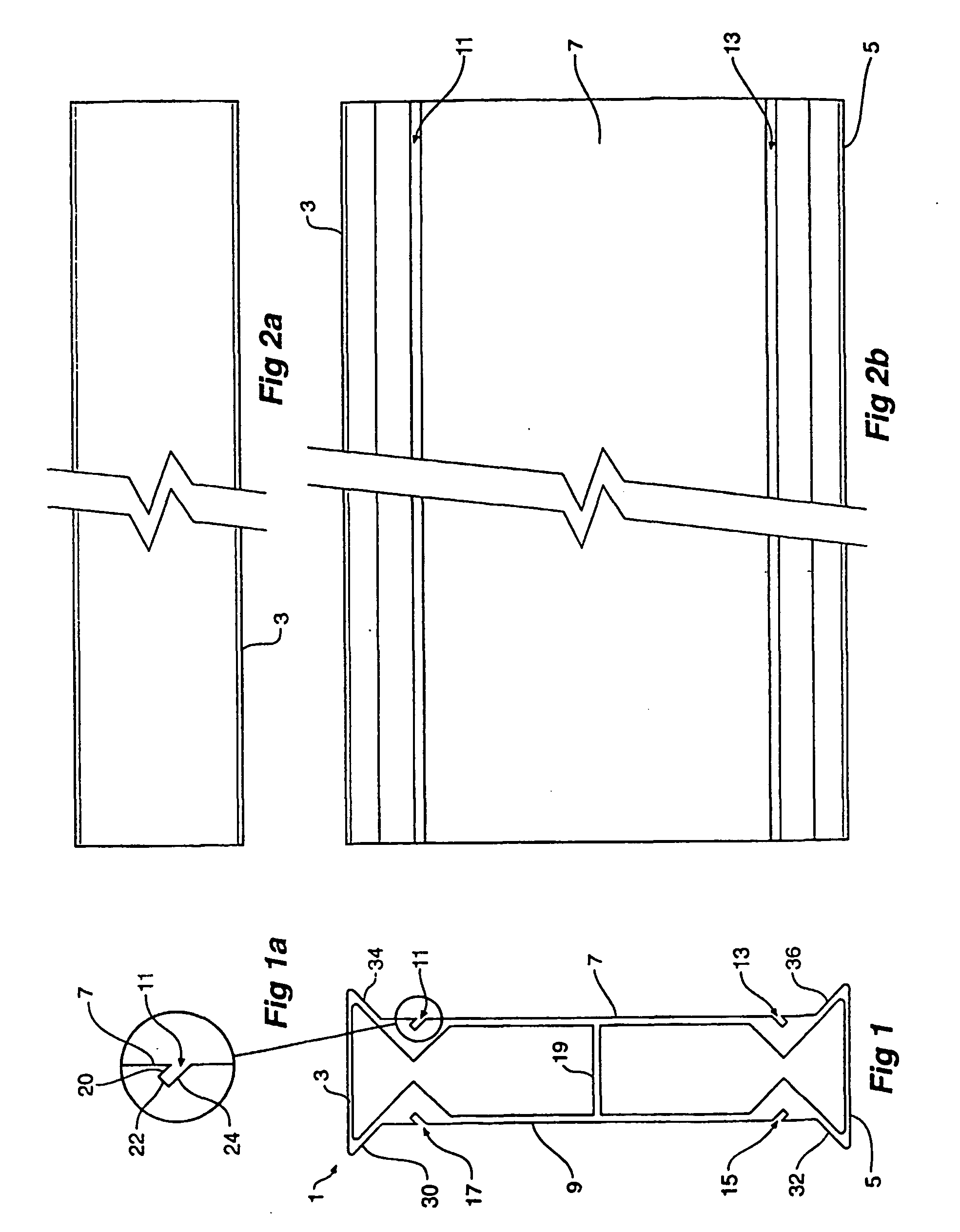
[0075] The invention is predicated on the finding that it is not necessary to use a buttress frame in order to secure side-form support members together and support side-forms. This avoids the need to use a support frame that may interfere with pouring or finishing panels. It also avoids the need to cart, haul and fix an excessive number of support members in situations where only one or two panels are to be poured.

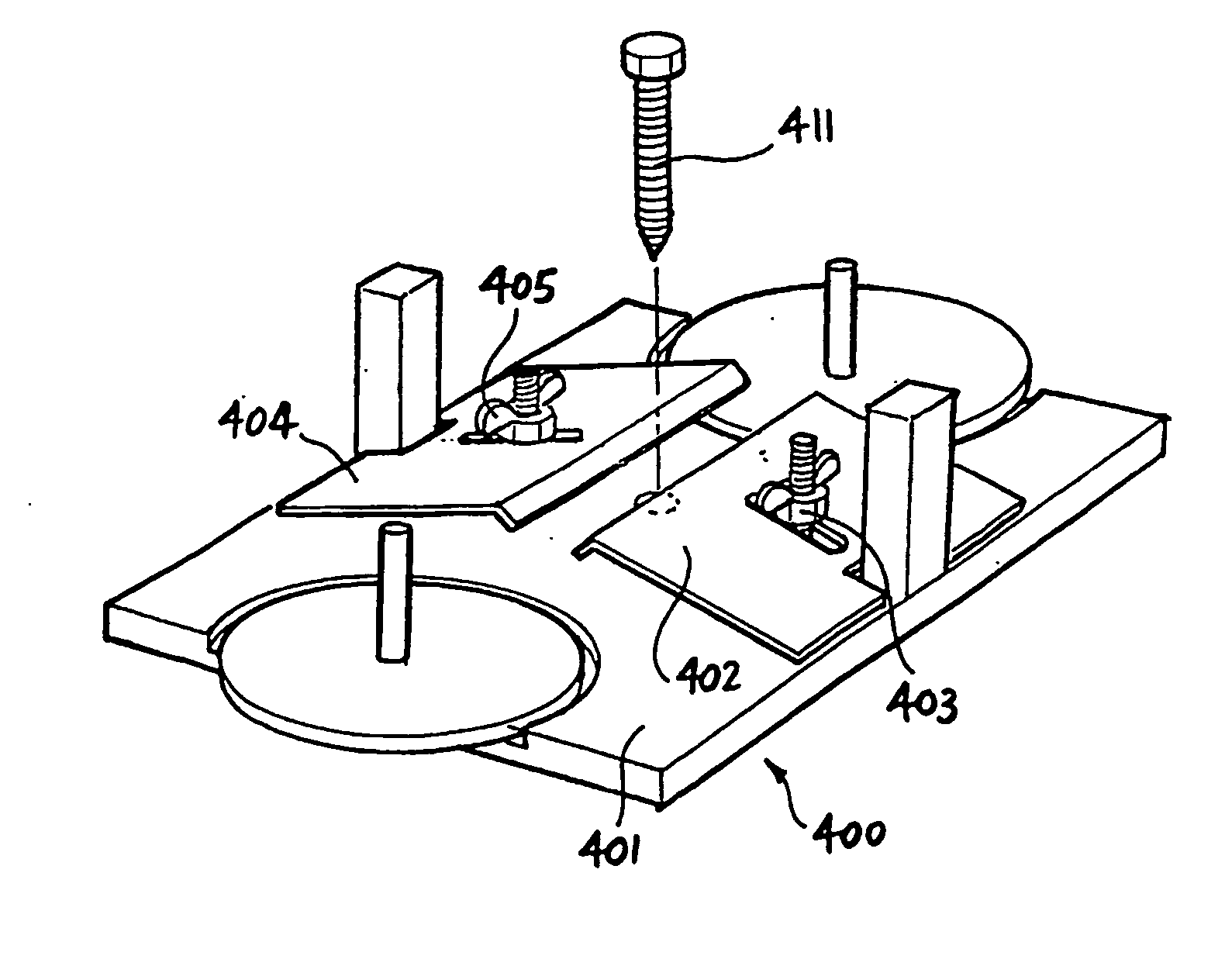
[0076] In essence the formwork of the invention uses a number of securing devices in order to secure a base support member to an underlying surface, and allow for the subsequent securing of another support member on top of the base support member. Additional support members (also known as risers) can also be secured to the structure by fixing them to an underlying riser.

[0077] However risers having square or rectangular cross section will not normally allow for the releasable securing of such support members to each other, and to an underlying surface without using a fi...


PUM

PropertyMeasurementUnit
Lengthaaaaaaaaaa
Structureaaaaaaaaaa
Shapeaaaaaaaaaa

Abstract

The present invention includes a formwork structure located on supporting surface, the structure having a side form perimeter including side form members, the perimeter defining a curable non-solid material retaining area; the formwork including side form support members that support the side form members, at least one of the side form support members being held in a fixed position relative to the supporting surface by a surface-to-member releasable securing device fixed to the supporting surface and which engages the side form support member, characterised in that the secured side form support member is adapted to permit another side form support member to be secured thereto by one or more releasable inter-member securing devices, which are separate to the surface-to-member securing device.

Description

FIELD OF INVENTION [0001] This invention relates to formwork for use in forming construction panels and structures. BACKGROUND OF INVENTION [0002] In the construction industry, panels and structures are either prepared on-site (as known as in-situ casting) or off-site (known as pre-casting). [0003] On-site casting is typically performed by constructing temporary formwork and pouring a curable non-solid material such as concrete into the formwork. Once the concrete has cured the formwork is removed. This method can be used to make walls, slabs or kerbs. [0004] Generally, the temporary formwork is formed from timber, in order to produce a low cost mould. In order to reduce costs in materials most formwork timbers are typically low-grade wood. These types of timbers are prone to weathering and there is often considerable variation between timbers. In order to reduce cost in labour the timbers are not recycled. A construction panel or structure cast in such formwork will normally have a...

Claims


Application Information

Patent Timeline
IPC IPC(8): B28B7/00E04G13/00E04G17/00E04G17/14
CPCB28B7/0014B28B7/0088E04G17/14E04G17/001E04G13/00
Inventor BRENNAN, JAMES ANDREW
Owner NICOLO ASSUNTA
Why Eureka
Try Eureka