Method and apparatus for molding rubber

a technology of rubber and molding equipment, which is applied in the field of methods and molding equipment, can solve the problems of deteriorating productivity in molding rubber products, affecting the production efficiency of rubber products, and unable to achieve ideal results of vulcanizing, so as to reduce deviations in blending compositions and improve molding productivity

Inactive Publication Date: 2005-03-24
TOYODA GOSEI CO LTD
View PDF9 Cites 10 Cited by
  • Summary
  • Abstract
  • Description
  • Claims
  • Application Information

AI Technical Summary

Benefits of technology

[0030] According to the present invention a rubber composition produced by kneading a rubber material and a predetermined blending material is made to be pelletted to provide a rubber pellet and this rubber pellet is delivered under pressure to an extrusion molding section by a pellet delivery section. Accordingly, flexibility between processes becomes possible, so that the present invention can be adapted to both a small item large volume production and large item small volume production and further, restrict deviations in a blending composition and yet to improve productivity in molding a rubber product.

Problems solved by technology

Thus the earlier method is performed by a batch type kneading by using an intensive mixer or a kneader, which tends to cause deviations in a blending rate of materials used, and further needs a lot of labor forces, thereby to deteriorate productivity in molding a rubber product.
According to the extrusion molding apparatus for continuous kneading described in the Patent Publication, however, since kneading of a non-vulcanizing rubber and a vulcanized agent in a kneading section each of which differs in a temperature condition and a product extrusion are continuously performed, an ideal result of product extrusion and an ideal result of vulcanizing can not be obtained.
And since the non-vulcanizing rubber is blended with the vulcanizing agent in the kneading section and thereafter, a product is extruded from the extrusion molding section directly connected to the kneading section, the only method of increasing a production amount is an increase of production speeds or production time, which provides the problem with lack of flexibility in productivity management.

Method used


Image

  • Method and apparatus for molding rubber
  • Method and apparatus for molding rubber
  • Method and apparatus for molding rubber

Examples


first embodiment

[0044] Embodiments of the present invention will be explained with reference to accompanying drawings as follows.

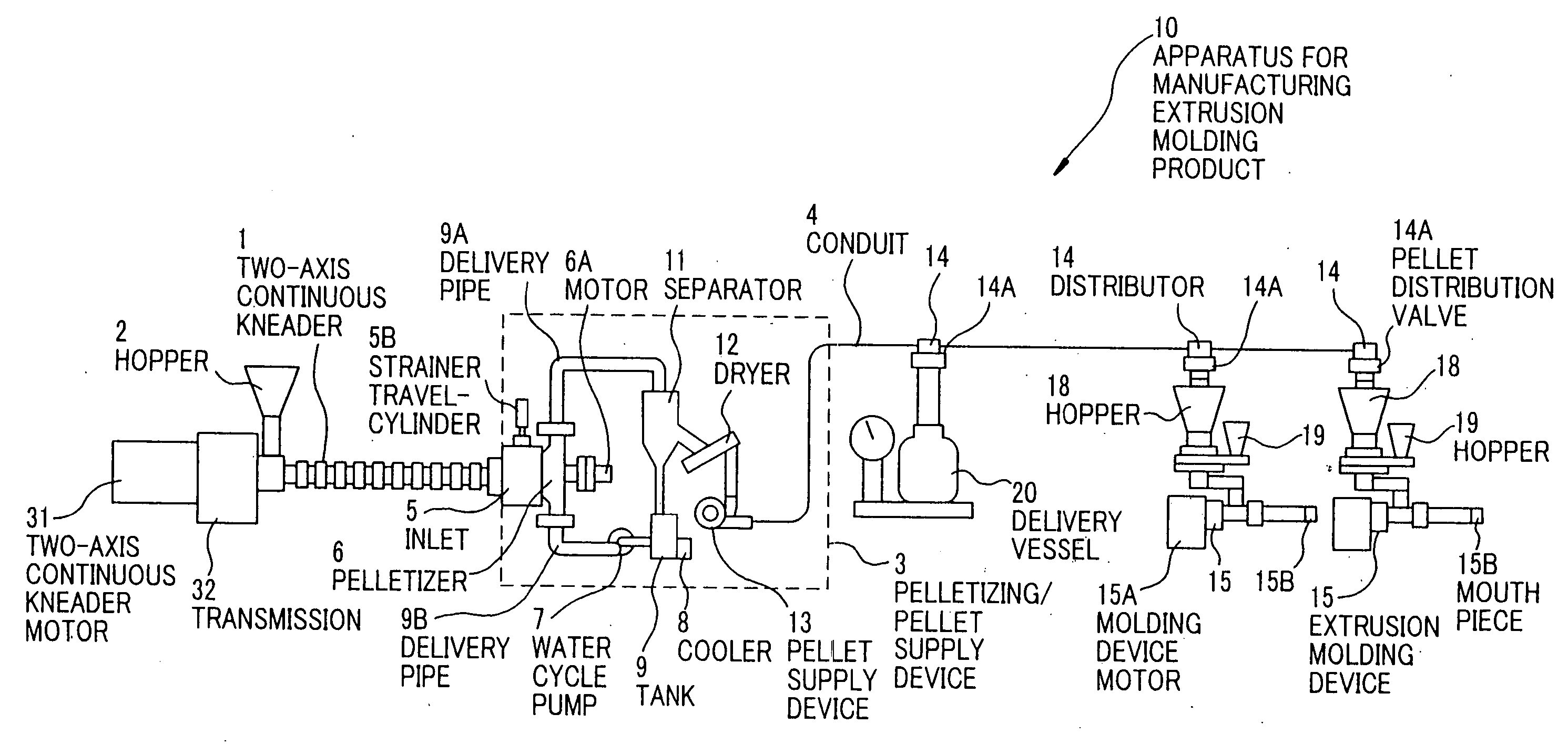
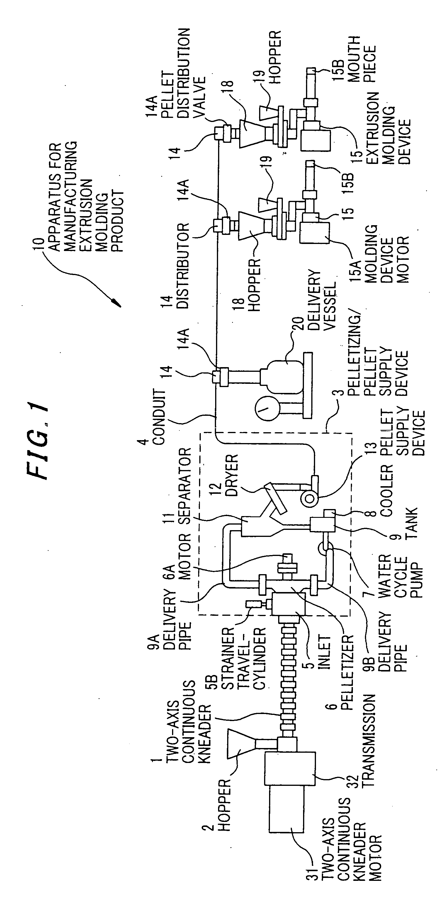
[0045]FIG. 1 is an entire construction view of an apparatus for manufacturing an extrusion molding product according to a first embodiment. The apparatus 10 for manufacturing the extrusion molding product includes a two-axis continuous kneading device 1, a hopper 2 as a supply port of raw rubber or the like, a two-axis continuous kneading device motor 31 providing rotation to a screw (not shown), a transmission 32 changing a screw rotation speed, a pelletizing / pellet delivery device 3, a pipe 4 equipped with a plurality of distributors 14 which distribute a pellet of a kneaded rubber composition conveyed though the pipe, a plurality of extrusion molding device 15 connected to the pipe 4 through the distributors 14, and a delivery vessel 20.

[0046] The distributor 14 includes a pellet distribution valve 14A which is controlled to be opened / closed by an actuator, and distr...

second embodiment

[0091]FIG. 6 is an entire construction view of an apparatus for manufacturing an extrusion molding product of a second embodiment. In the following explanation, components in the second embodiment identical to those in the first embodiment are referred to as identical numerals. The second embodiment differs from the first embodiment in that a storage tank 24 is connected through the distributor 14 to the conduit 4, the conduit 4 is connected to a pellet delivery device 25 disposed under the storage tank 24, and the extrusion molding device 15 is connected through the distributor 14.

[0092] Accordingly the pellet from the pelletizing / pellet delivery device 3 is stored in the storage tank 24 through the distributor 14, delivered under pressure in the pellet delivery device 25 to be delivered inside the conduit 4 and then supplied to the extrusion molding device 15.

[0093] An operation of the second embodiment will be explained as follows.

[0094] The two-axis continuous kneader 1 forms...

third embodiment

[0097]FIG. 7A is an entire construction view of an apparatus for manufacturing an extrusion molding product according to a third embodiment. FIG. 7B is an enlarged view of a part in FIG. 7A. In the third embodiment, as shown in FIG. 7A, the apparatuses 10A, 10B for manufacturing the extrusion molding product are installed. An extrusion opening 15B of the extrusion molding device 15 in one apparatus 10A for manufacturing the extrusion molding product and an extrusion opening 15B of the extrusion molding device 15 in the other apparatus 10B for manufacturing the extrusion molding product are connected to a common front end 151 as shown in FIG. 7B to form a weather strip 40 including a sliding contact face 40A on a surface of the base 40B. Namely the apparatus 10A for manufacturing the extrusion molding product supplies the rubber material from the mouth piece 15b through a reduced section 330 and a front end 331 to form the sliding contact face 40A and on the other hand, the apparatus...


PUM

PropertyMeasurementUnit
pressureaaaaaaaaaa
shapeaaaaaaaaaa
flexibleaaaaaaaaaa

Abstract

A two-axis continuous kneader 1 kneads a raw rubber, a reinforcing agent such as a carbon black, a softener such as a process oil, and the like by a screw, and at the same time sends them out in the front end direction and to the pelletizing/pellet delivery device 3. The pelletizing/pellet delivery device 3 manufactures the rubber pellet to be pressure-supplied to the extrusion molding device 15 through the conduit4. The extrusion molding device 15 kneads the rubber pellet supplied to the hopper 18 and the additive such as the vulcanized agent supplied to the hopper 19 by the screw to extrude the rubber pellet for a desired product.

Description

[0001] The present application is based on Japanese patent application No. 2003-329662, the entire contents of which are incorporated herein by reference. BACKGROUND OF THE INVENTION [0002] 1 . Field of the Invention [0003] The present invention relates to a method and an apparatus for molding rubber and in particular, to a method and an apparatus for molding rubber which performs operations from kneading of a rubber material to molding thereof based upon a series of steps. [0004] 2. The Related Art of the Invention [0005] As an earlier method of molding a rubber product such as a tread of a tire or a weather strip for a vehicle there is generally adopted a method where raw rubber, a reinforcing agent, a filling agent, a softener are put in a kneader such as an intensive mixer for kneading, to mold a sheet and thereafter, this molded sheet, together with a vulcanized agent is put into a molding device to provide a product in a desired shape (for instance, weather strip). [0006] Thus...

Claims


Application Information

Patent Timeline
Patent Type & Authority Applications(United States)
IPC IPC(8): B29C31/04B29B7/74B29B9/06B29C48/12B29C48/285B29K7/00B29K9/00
CPCB29B7/7495B29B9/065B29C47/0004B29C47/003B29K2105/16B29K2021/00B29C47/1045B29C47/1081B29C47/10B29C48/297B29C48/022B29C48/12B29C48/285B29C48/2886B29B7/48B29B7/748B29B9/12B29B9/16B29B7/728B29B7/60B29B7/007B29B7/7466
Inventor KURASHIGE, MITSUONARITA, TAKUMOKITA, TOMOAKIKATSUMURA, GUNPEI
Owner TOYODA GOSEI CO LTD
Why Eureka
Try Eureka