Phase modulation apparatus and phase modulation method

Inactive Publication Date: 2005-03-24
HAMAMATSU PHOTONICS KK
View PDF2 Cites 30 Cited by
  • Summary
  • Abstract
  • Description
  • Claims
  • Application Information

AI Technical Summary

Benefits of technology

[0049] The computer executes the program to only add the wavefront-distortion correction phase pattern to the desired phase pattern, thereby obtaining a wavefront-distortion corrected phase pattern. Accordingly, the wavefront-distortion corrected phase pattern can be quickly generated by performing simple computation.
[0050] It is preferable that a program according to the present invention further includes a process of inverting a sign of a wavefront-distortion phase pattern indicating a phase of the wavefront distortion of the light, thereby generating the wavefront-distortion correction phase pattern. Since the wavefront-distortion correction phase pattern can be generated merely by inverting the sign of the wavefront-distortion phase pattern, no complex computation is required. The wavefront-distortion correction phase pattern can be quickly generated.
[0051] The present invention provides a computer-readable recording medium storing a program executed by a computer storing: a process of preparing a desired phase pattern; a process of preparing a wavefront-distortion correction phase pattern for correcting a wavefront distortion of light; and a process of adding the desired phase pattern to the wavefront-distortion correction phase pattern, ther

Problems solved by technology

In order to manufacture a phase modulated spatial light modulator that has a reading-side substrate with high flatness, expensive materials must be used, which makes manu

Method used


Image

  • Phase modulation apparatus and phase modulation method
  • Phase modulation apparatus and phase modulation method
  • Phase modulation apparatus and phase modulation method

Examples


first embodiment

[0075] A laser process apparatus and a laser process method, both according to the first embodiment of the invention, will be described with reference to FIGS. 1 to 9(B).

[0076] The present embodiment relates to a laser process apparatus and a laser process method, in which a process target T is processed by a laser beam to be formed with any desired pattern.

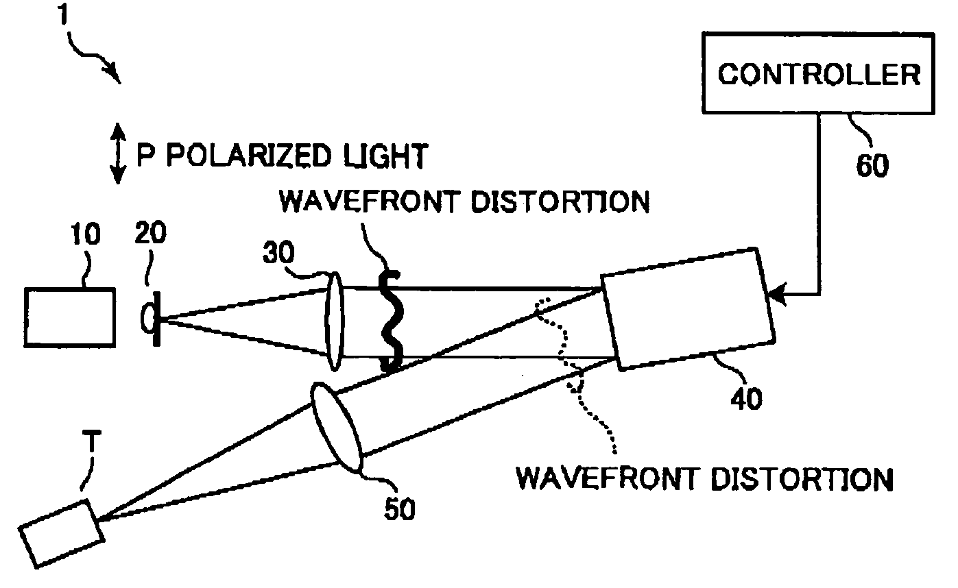
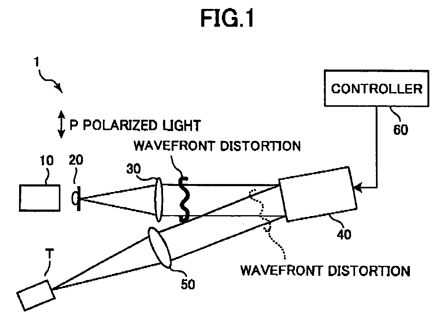
[0077] As shown in FIG. 1, the laser process apparatus 1 according to the first embodiment includes a reading light source 10, a spatial filter 20, a collimate lens 30, a phase modulation module 40, a Fourier lens 50, and a controller 60.

[0078] The reading light source 10 is constituted by an He—Ne laser to generate coherent reading light. The reading light emitted from the reading light source 10 has an almost uniform phase distribution in the cross section. The reading light is a linear polarization having a polarization plane parallel to the plane of FIG. 1.

[0079] The spatial filter 20 removes excessive diffracted waves an...

second embodiment

[0178] A laser process apparatus 1 and a laser process method according to the second embodiment of the invention will be described with reference to FIG. 12.

[0179] In this embodiment, as shown in FIG. 12, the controller 60 further includes a distortion-correction pattern input unit 60k. The distortion-correction pattern input unit 60k is constituted by either a recording-medium reading device 65 or an NCU 67. The unit 60k receives the distortion correction pattern C (x, y) from the network 68 or a recording medium 74 such as a flexible disk, a CD-ROM or a DVD to store the distortion correction pattern in the distortion-correction pattern memory unit 60d. In the present embodiment, the controller 60 does not have the distortion pattern input unit 60h, the distortion pattern memory unit 60b and the distortion-correction pattern generating unit 60c. The controller 60 does not perform the distortion-correction pattern generating process (FIG. 9(A), FIG. 9(B)) which is carried out in t...

third embodiment

[0194] A laser process apparatus 1 and a laser process method according to the third embodiment of the invention will be described with reference to FIG. 13.

[0195] In the present embodiment, as shown in FIG. 13, the controller 60 has a distortion-correction pattern input unit 60k, similarly to the second embodiment. As in the first embodiment, the controller 60 includes a distortion pattern input unit 60h, a distortion pattern memory unit 60b, and a distortion-correction pattern generating unit 60c.

[0196] In this embodiment, a manufacturer obtains a phase distortion correction pattern C150 (x, y) for correcting the wavefront distortion Φ150 (x, y) (=−C150 (x, y)) resulting from the reading-side transparent substrate 150b of PAL-SLM 150, before arranging the phase modulating module 40 to manufacture the laser process apparatus 1 in the same manner as that of the second modification of the second embodiment. That is, the manufacturer first arranges the phase modulation module 40 or ...


PUM


Abstract

An adder unit (60e) reads a desired CGH pattern from a pattern memory unit (60a) and a phase distortion correction pattern from a distortion-correction pattern memory unit (60d) and adds both patterns together to generate a phase distortion corrected pattern. A control unit (60g) controls a phase modulation module (40) in accordance with the phase distortion corrected pattern. Accordingly, phase-modulated light based on the desired phase pattern can be generated precisely, easily and quickly.

Description

TECHNICAL FIELD [0001] The present invention relates to a phase modulating apparatus, a phase modulating method, a program for performing the phase modulating method, and a recording medium in which the program is recorded. More particularly, the invention relates to a phase modulating apparatus and phase modulating method for modulating the phase of a laser beam by using a phase modulated spatial light modulator, a program for performing the phase modulating method, and a recording medium in which the program is recorded. BACKGROUND ART [0002] There has been proposed a phase modulating apparatus that uses a phase modulated spatial light modulator to modulate the phase of a laser beam in accordance with a phase pattern calculated by a computer. In the phase modulating apparatus, a phase pattern is written to the phase modulated spatial light modulator to be irradiated by a laser beam, so that phase modulation light modulated with the phase pattern is generated. [0003] Japanese Paten...

Claims


Application Information

Patent Timeline
IPC IPC(8): G03H1/08G03H1/22
CPCG03H1/08G03H1/2205G03H1/2294G03H2001/0072G03H2001/0094G03H2001/085G03H2225/32G03H1/2249G03H2210/20G03H2001/0216
Inventor IGASAKI, YASUNORIFUKUCHI, NORIHIRO
Owner HAMAMATSU PHOTONICS KK
Why Eureka
Try Eureka