

Optical recording medium
a technology of optical recording medium and optical recording medium, which is applied in the direction of optical recording/reproducing/erasing methods, instruments, and thermography, can solve the problems of worse jitter and worse jitter, and achieve satisfactory jitter and low heat interference
- Summary
- Abstract
- Description
- Claims
- Application Information
AI Technical Summary
Benefits of technology
Problems solved by technology
Method used
Image

Examples
example 1
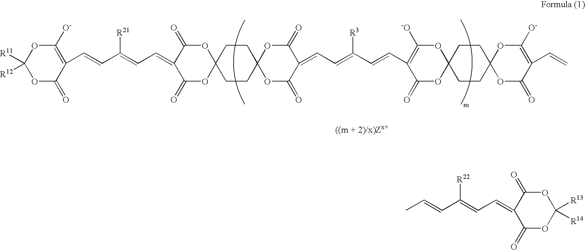
By injection molding, a polycarbonate resin was formed into a substrate having a thickness of 0.6 mm and a diameter of 120 mm and having a spiral groove (depth: 130 nm, width: 300 nm, track pitch: 0.74 μm). A coating solution was prepared by dissolving 1.0 g of the following dye A and 0.5 g of the following dye B in 100 ml of 2,2,3,3-tetrafluoropropanol. The coating solution was coated by a spin coating met on a surface of the substrate on which grooves were formed hod to form a recording layer. Then, a reflecting layer having thickness of about 150 nm was formed on the recording layer by sputtering silver. Thereafter, the substrate and a dummy substrate were bonded to each other using an ultraviolet-curable resin as an adhesive to prepare an optical disk (optical recording medium).
example 2
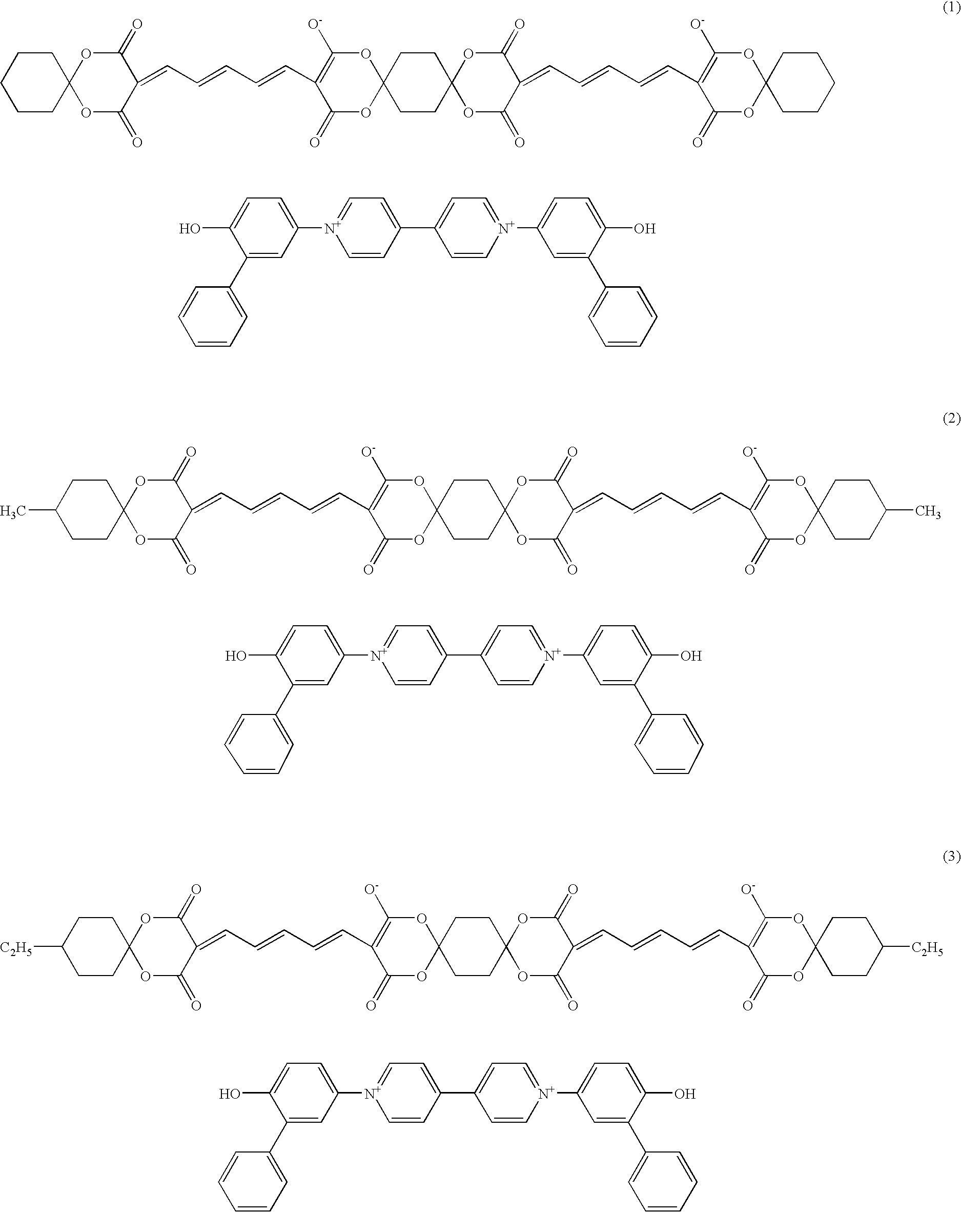
By injection molding, a polycarbonate resin was formed into a substrate having a thickness of 0.6 mm and a diameter of 120 mm and having a spiral groove (depth: 120 nm, width: 300 nm, track pitch: 0.74 μm). A coating solution was prepared by dissolving 0.1875 g of the dye B and 1.0625 g of the following dye C in 100 ml of 2,2,3,3-tetrafluoropropanol. The coating solution was coated by a spin coating method on a surface of the substrate on which groove was formed to form a recording layer. Then, a reflecting layer having thickness of about 120 nm was formed on the recording layer by sputtering silver. Thereafter, the substrate and a dummy substrate were bonded to each other using a UV-curable resin as a adhesive to prepare an optical disk (optical recording medium).
example 3
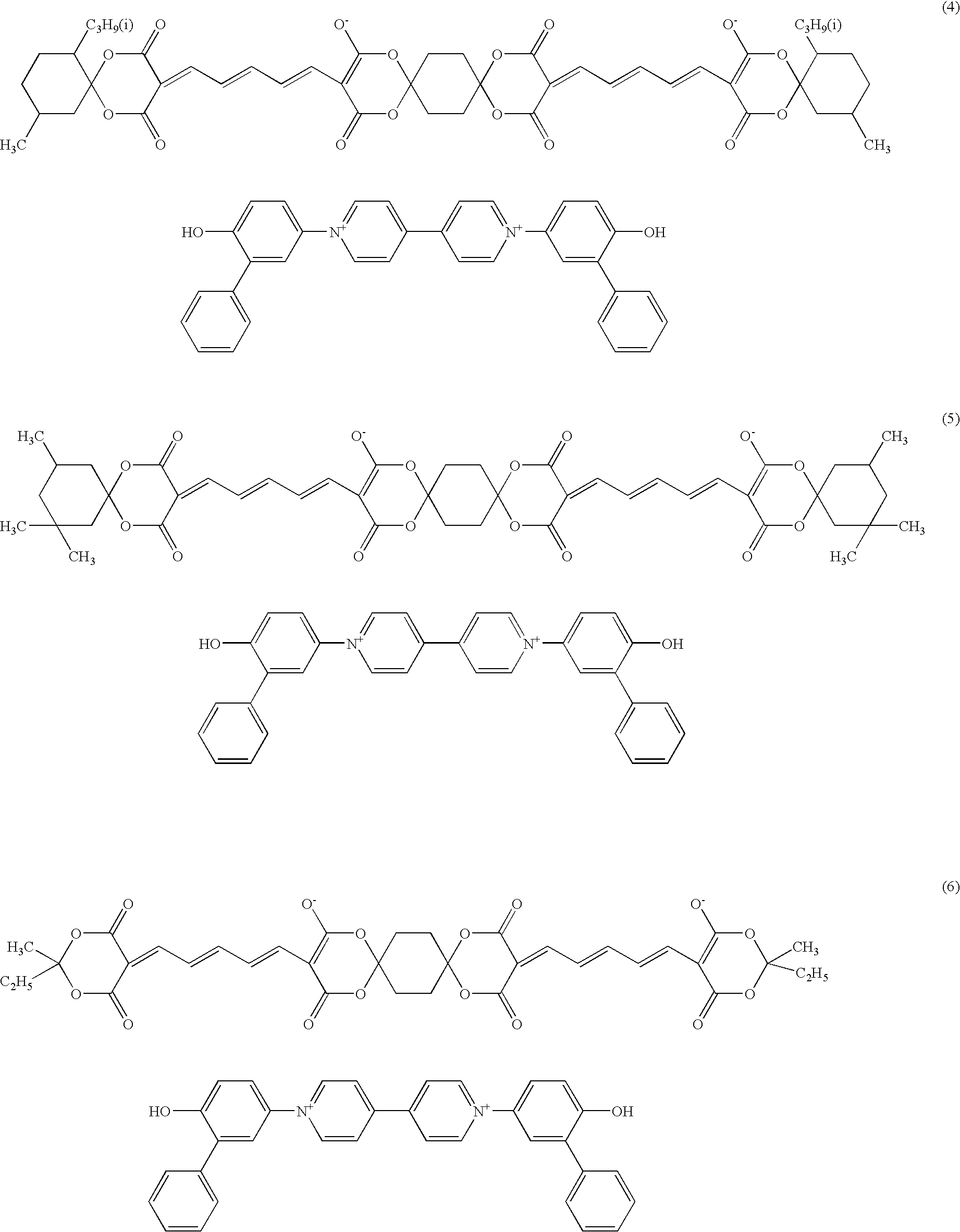
An optical disk was prepared in the same way as in Example 2 except that the following dye D was used in place of the dye C.
PUM
| Property | Measurement | Unit |
|---|---|---|
| height | aaaaa | aaaaa |
| pit length | aaaaa | aaaaa |
| pit length | aaaaa | aaaaa |
Abstract
Description
Claims
Application Information