Rolling element retainer and rolling bearing assembly using the same

Inactive Publication Date: 2005-03-24
NTN CORP
View PDF6 Cites 19 Cited by
  • Summary
  • Abstract
  • Description
  • Claims
  • Application Information

AI Technical Summary

Benefits of technology

[0044] According to the combined use of the angular ball bearing assembly and the nozzle member, the lubricant oil supplied from the nozzle member can be blown to the outer peripheral surface of the inner race of the angular ball bearing assembly and, hence, the lubricant oil can be efficiently supplied into the bearing assemb

Problems solved by technology

Also, unless oil drainage (purge of the air/oil mixture) takes place smoothly, the lubricant oil will accumulate within the rolling bearing assembly, accompanied by increase of the stirring drag of the lubricant oil, which leads to increase of the temperature rise.
However, since the inner race of the angular ball bearing assembly is used to support the load on a portion of the raceway surface adjacent the bearing front side f (and, hence, has a surface of contact with the rolling elements), reduction of the outer diameter of the inn

Method used


Image

  • Rolling element retainer and rolling bearing assembly using the same
  • Rolling element retainer and rolling bearing assembly using the same
  • Rolling element retainer and rolling bearing assembly using the same

Examples


first embodiment

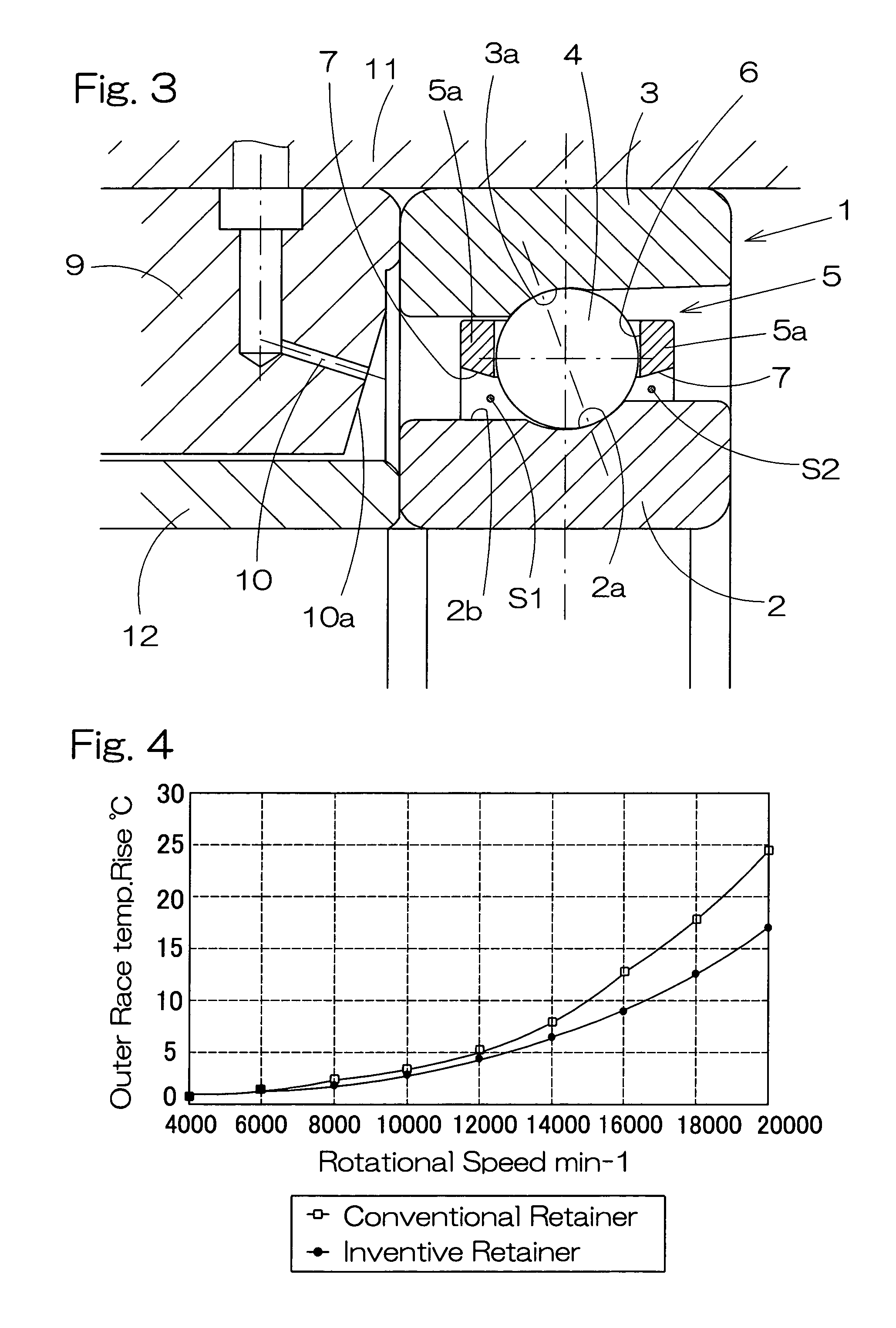
[0089]FIG. 4 is a chart showing results of tests conducted to determine to what extent the temperature of the outer race increases in the rolling bearing assembly 1 of the foregoing embodiment of the present invention and, also, in the conventional rolling bearing assembly 51 shown in and described with reference to FIGS. 19 and 20, while the air / oil lubrication was performed during the operation of the rolling bearing assembly. The conventional rolling bearing assembly 51 is of a type, in which the rolling element retainer 55 has the inclined annular faces 57 formed merely by chamfering the opposite end portions of the inner peripheral surface of the retainer 55 and is, except for this feature, similar in structure to the rolling bearing assembly 1 shown and described in connection with the present invention.

[0090] The specification of the retainers 5 and 55 and the test conditions are shown in Tables 1 and 2, respectively.

TABLE 1Retainer SpecificationsRetainerRetainer5 (FIG. 1)5...

third embodiment

[0104] According to the present invention, the lubricant oil supplied from the nozzle member 9 is jetted onto that portion of the outer peripheral surface of the inner race 2 of the angular ball bearing assembly 21 to efficiently lubricate the inside of the bearing assembly 21. Since, as hereinabove described, the presence of the annular tapered surface area 3b adjacent the bearing rear side g facilitates the drainage of the lubricant oil from the gap a delimited between the outer race 3 and the retainer 5, the heat generation resulting from the stirring of the lubricant oil can advantageously be suppressed to thereby increase the lubricity.

[0105] Referring now to FIG. 10, there is shown a spindle device 40 utilizing the angular ball bearing assembly 21 of FIG. 7. The spindle device 40 is generally utilized in machine tools and includes a spindle 15 having one end 15a to which a chuck of a tool or a work is mounted. This spindle 15 is rotatably supported by a plurality of, for examp...

second embodiment

[0109] A fourth preferred embodiment of the present invention will now be described with particular reference to FIGS. 11 an 12. The rolling bearing assembly shown therein is an angular ball bearing assembly 21A similar in structure to the angular ball bearing assembly 21 (FIG. 7) of the present invention.

[0110] However, the angular ball bearing assembly 21A differs from the angular ball bearing assembly 21 in that, in place of the annular tapered surface area 3b formed in the shoulder portion A of the inner peripheral surface of the outer race 3 shown in FIG. 7, a portion B1 of the outer peripheral surface of the retainer 5 on one side of each pocket-formed portion (or a circumferential portion in which the pockets are formed and having a width corresponding to a pocket diameter) adjacent the rear side g of the outer race 3 and a portion B2 of the outer peripheral surface of the retainer 5 on the opposite side of the respective pocket-formed portion adjacent the bearing front side ...


PUM


Abstract

To secure a load bearing capability along with a smooth supply and drainage of a lubricant oil into and from a rolling bearing assembly, a retainer and the rolling bearing assembly provided with such retainer are of a design in which the retainer (5) includes an annular wing portion (5a) and a plurality of pillars (5b) extending from circumferential locations of the annular wing portion (5a) and formed with a pocket (6) between the neighboring pillars (5b) for rollingly retaining rolling elements (4) of the rolling bearing assembly. The annular wing portion (5a) has an inner peripheral surface formed to define an inclined annular face (7). This inclined annular face (7) is deployed over a substantially entire width of the annular wing portion (5a) in an axial direction of the retainer (5) and is inclined to flare axially outwardly to have a diameter decreasing towards a mid-center portion of the retainer (5) in the axial direction.

Description

BACKGROUND OF THE INVENTION [0001] 1. Field of the Invention [0002] The present invention relates to a rolling element retainer for a rolling bearing assembly of a kind generally employed in generic industrial machines such as a spindle device for a machine tool, to a rolling bearing assembly utilizing such rolling element retainer and to a lubricating structure for the rolling bearing assembly. [0003] 2. Description of the Prior Art [0004] In rolling bearing assemblies, the purpose of lubrication is to prevent a direct metal-to-metal contact in the presence of a thin oil film formed on rolling surfaces and sliding surfaces and, by so doing, the following effects can be obtained: [0005] (1) Minimization of friction and frictional wear, [0006] (2) Purging of heat evolved as a result of friction, [0007] (3) Increase of the lifetime of the rolling bearings, [0008] (4) Prevention of rusting, and [0009] (5) Prevention of foreign matter from being trapped in the rolling bearings. [0010] I...

Claims


Application Information

Patent Timeline
IPC IPC(8): F16C19/16F16C33/38F16C33/58F16C33/66
CPCF16C19/163F16C33/3843F16C33/6681F16C33/6662F16C33/58F16C19/548F16C33/583
Inventor UEDA, KEIICHIUENO, KAORUYONEZAWA, TADAYOSHI
Owner NTN CORP
Why Eureka
Try Eureka