Method for three plane interleaved acquisition for three dimensional temperature monitoring with MRI

Inactive Publication Date: 2005-03-24
GE MEDICAL SYST GLOBAL TECH CO LLC
View PDF2 Cites 61 Cited by
  • Summary
  • Abstract
  • Description
  • Claims
  • Application Information

AI Technical Summary

Benefits of technology

Accordingly, what is needed is a method that utilizes an MR imaging system for effectively monitoring the temperature in three dimensions. The present invention provides for such a method of three dimensional temperature monitoring. It has the advantages of being highly efficient in acquisition and being straightforward in presentation. The present invention is based

Problems solved by technology

However, a regular three dimensional acquisition is time consuming, so the spatial resolution or the temporal resolution will be comprom

Method used


Image

  • Method for three plane interleaved acquisition for three dimensional temperature monitoring with MRI
  • Method for three plane interleaved acquisition for three dimensional temperature monitoring with MRI
  • Method for three plane interleaved acquisition for three dimensional temperature monitoring with MRI

Examples


Embodiment Construction

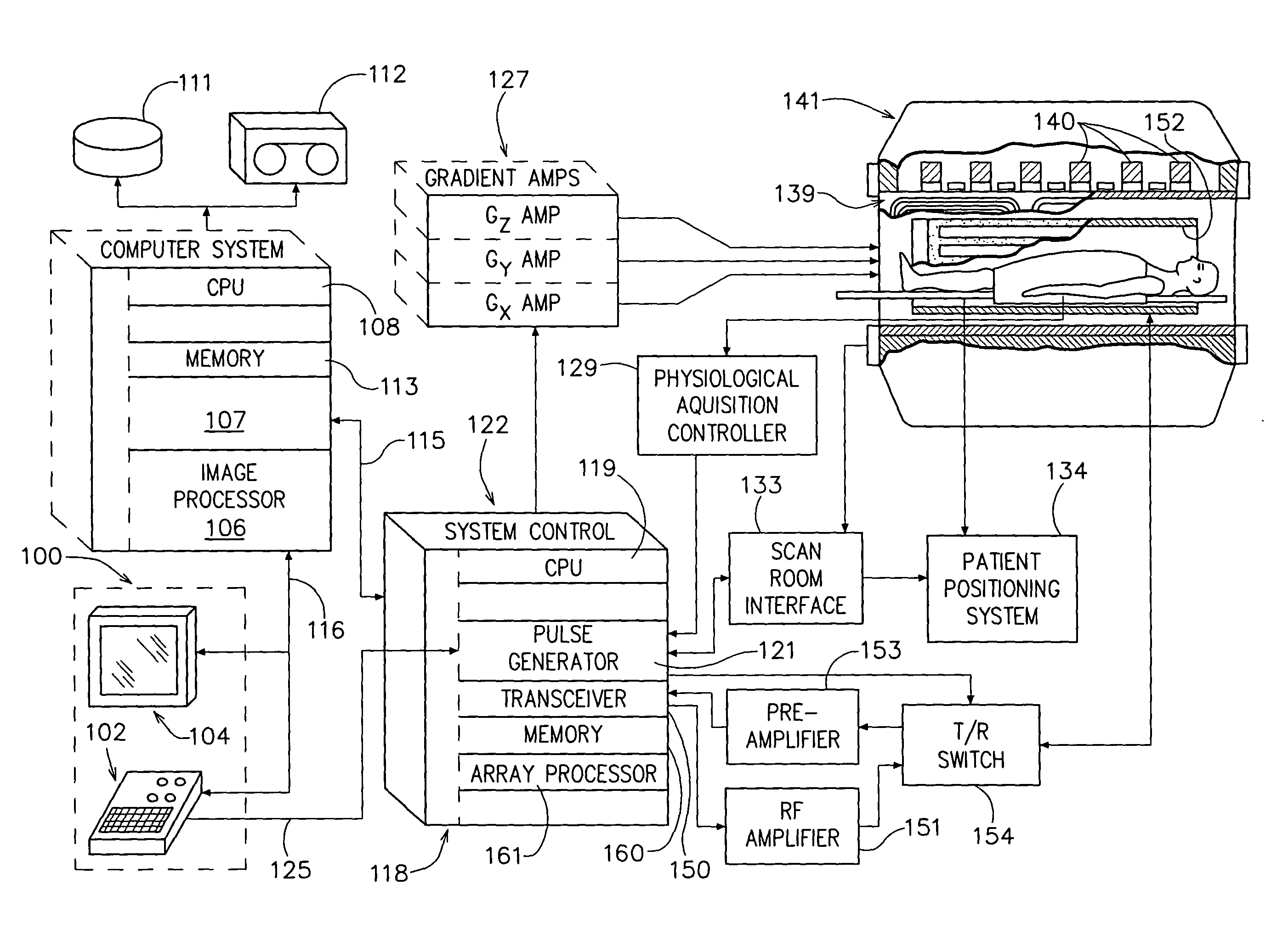
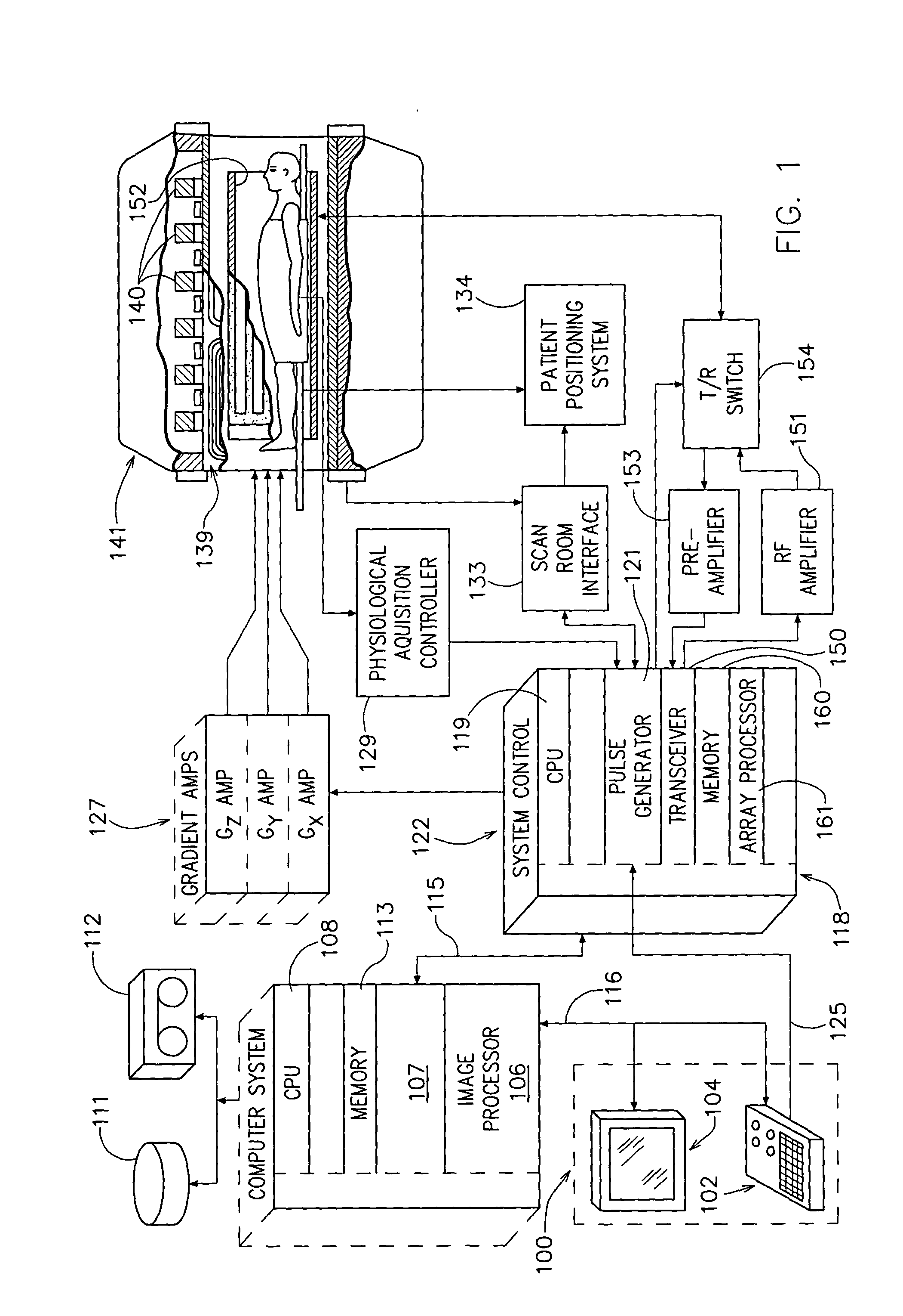
Referring now to the drawings in detail wherein like numbered elements refer to like elements throughout, FIG. 1 is a block diagram showing the components of an MRI system. The operation of the system is controlled by a console 100 which includes a keyboard, a control panel 102 and a display. The console 100 communicates through a link 116 with a separate computer system 107 that enables an operator to control the production and display of images on the screen 104. The computer system 107 includes a number of modules which communicate with each other through a backplane 118. These include an image processor module 106, a CPU module 108 and a memory module 113, known in the art as a frame buffer for storing image data arrays. The computer system 107 is linked to a disk storage 111 and a tape drive 112 through a high speed serial link 115.

The system control 122 includes a set of modules connected together by a backplane. These include a CPU module 119 and a pulse generator module 1...


PUM


Abstract

The present invention provides for a method of three dimensional temperature monitoring based in hyperthermic procedures, the heat dissipation, and therefore, temperature variations, does not change dramatically over a spatial region and, second, temperature change, which manifests itself as the phase change, has different characteristics compared to the anatomic magnitude image. Therefore the present invention exploits these facts to provide a method for acquiring the temperature map of three orthogonal planes nearly simultaneously.

Description

BACKGROUND OF THE INVENTION The present invention relates generally to a magnetic resonance imaging (MRI) methods and devices, and more specifically, to a method for using MRI to measure temperature change in either liquid or tissue. Thermal energy deposition is often used in medicine as a means of necrosing diseased tissues. Lasers, radio frequency antennas and ultrasonic transducers are examples of devices used for the deposition of thermal energy for therapy. However, regardless of the therapeutic regimen used, it is desirable to have a means of guiding and monitoring this energy deposition to assure the energy is applied in the proper location and to verify that appropriate energy levels are used to prevent undertreatment or overtreatment for two main reasons. The first is to ensure that the diseased tissue has been exposed to an adequate temperature-time treatment to induce necrosis over the entire diseased volume. The second is to ensure that the surrounding healthy tissue i...

Claims


Application Information

Patent Timeline
IPC IPC(8): A61B5/00A61B5/055G01R33/48
CPCA61B5/015G01R33/4804A61B5/055
Inventor ZHOU, YONG
Owner GE MEDICAL SYST GLOBAL TECH CO LLC
Why Eureka
Try Eureka