Bladeless optical obturator

a technology of optical obturators and blades, which is applied in the field of trocar systems, can solve the problems of increased operating room costs and procedural time, large trocar site defects, and damage to vessels and organs, and achieve the effect of facilitating frictional engagemen

Active Publication Date: 2005-03-24
APPL MEDICAL RESOURCES CORP
View PDF79 Cites 247 Cited by
  • Summary
  • Abstract
  • Description
  • Claims
  • Application Information

AI Technical Summary

Benefits of technology

[0012] In another aspect of the invention, the bladeless obturator further comprises a lock disposed at the proximal end of the shaft to frictionally lock the optical instrument in an axial position in the shaft. The lock operates to prevent the optical instrument from moving axially relative to the shaft while allowing the optical instrument to rotate freely about the shaft. The lock can be constructed from a plastic material including polycarbonate. The lock can be a multi-finger collet having an inner diameter smaller than an outer diameter of the optical instrument wherein the fingers of the collet spread open during insertion of the optical instrument providing fricti

Problems solved by technology

While the sharp blades, sharp edges and piercing points have facilitated a reduced penetration force, they have also caused larger trocar site defects.
These trocar site defects may have to be sutured closed resulting in increased operating room costs and procedural time.
Moreover, once the abdominal wall has been penetrated, the sharp blades, sharp edges and piercing points of the obturator may still cause damage to the vessels and o

Method used


Image

  • Bladeless optical obturator
  • Bladeless optical obturator
  • Bladeless optical obturator

Examples


Embodiment Construction

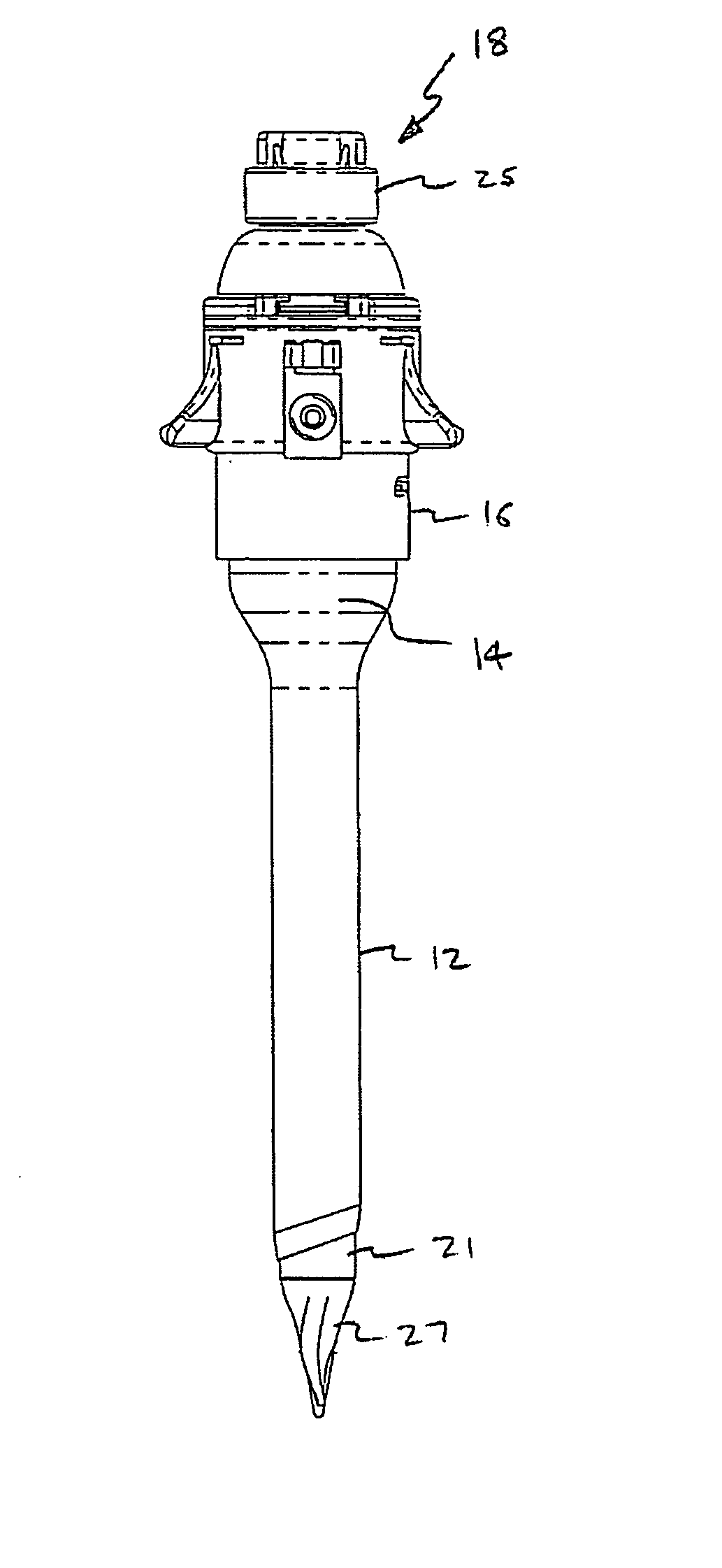
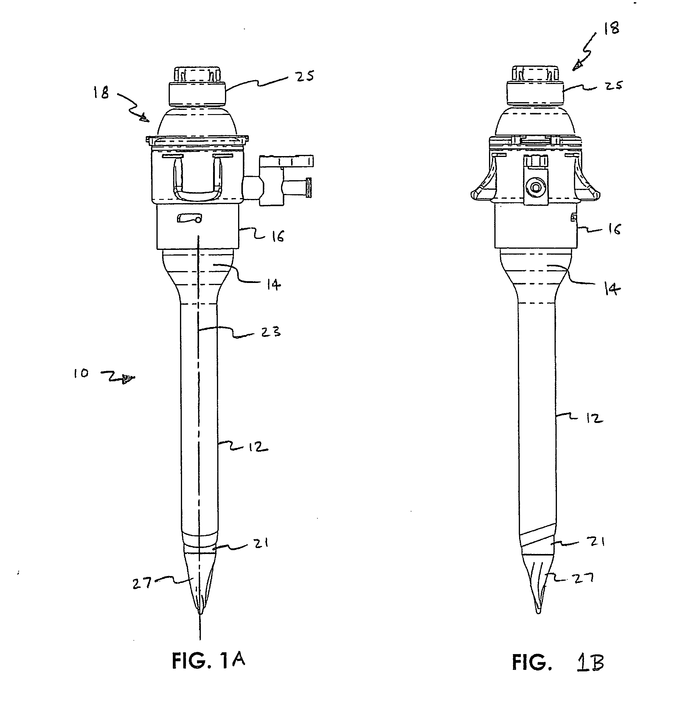
[0047] A trocar system is illustrated in FIG. 1 and is designated by reference numeral 10. This system includes a cannula 12, defining a working channel 14, and a valve housing 16. The system 10 also includes an obturator 18 having a shaft 21 extending along an axis 23. A handle 25 is disposed at a proximal end of the shaft 21 while a blunt tip 27 is disposed at a distal end of the shaft 21. The shaft 21 of the obturator 18 is sized and configured for disposition within the working channel 14 of the cannula 12. With this disposition, the obturator 18 can be placed across a body wall such as the abdominal wall to provide the cannula 12 with access across the wall and into a body cavity, such as the peritoneal or abdominal cavity. The blunt tip 27 serves to direct the obturator 18 through the abdominal wall and the peritoneum, and can be removed with the obturator 18 once the cannula 12 is operatively disposed with the working channel 14 extending into the abdominal cavity. The diamet...


PUM


Abstract

The invention is directed to a bladeless trocar obturator to separate or divaricate body tissue during insertion through a body wall. In one aspect, the obturator of the invention comprises a shaft extending along an axis between a proximal end and a distal end; and a bladeless tip disposed at the distal end of the shaft and having a generally tapered configuration with an outer surface, the outer surface extending distally to a blunt point with a pair of side sections having a common shape and being separated by at least one intermediate section, wherein each of the side sections extends from the blunt point radially outwardly with progressive positions proximally along the axis, and the shaft is sized and configured to receive an optical instrument having a distal end to receive an image of the body tissue. With this aspect, the tapered configuration facilitates separation of different layers of the body tissue and provides proper alignment of the tip between the layers. The side sections include a distal portion and a proximal portion, the distal portion of the side sections being twisted radially with respect to the proximal portion of the side sections. The intermediate section includes a distal portion and a proximal portion, the distal portion of the intermediate section being twisted in a first radial direction and the proximal portion of the intermediate section being twisted in a second radial direction opposite the first radial direction.

Description

[0001] This is a continuation-in-part of co-pending U.S. application Ser. No. 10 / 489,403, filed on Mar. 11, 2004, which is a 371 of International Application No. PCT / US02 / 06759, filed on Mar. 4, 2002 based on Provisional Application Ser. No. 60 / 324,613, filed on Sep. 24, 2001, and entitled “Bladeless Obturator,” all of which are fully incorporated herein by reference. This continuation-in-part application further claims priority to provisional application Ser. No. 60 / 508,390, filed on Oct. 3, 2003, entitled “Bladeless Optical Obturator,” which is fully incorporated herein by reference.BACKGROUND OF THE INVENTION [0002] 1. Field of the Invention [0003] This invention generally relates to trocar systems including obturators and, more specifically, to blunt tip obturators having hollow shafts for insertion of optical instruments. [0004] 2. Discussion of the Prior Art [0005] Trocar systems have been of particular advantage in facilitating less invasive surgery across a body wall and wit...

Claims


Application Information

Patent Timeline
IPC IPC(8): A61BA61B17/00A61B17/32A61B17/34A61B19/00
CPCA61B17/3417A61B2017/3464A61B17/3474A61B17/3496A61B19/5212A61B2017/0046A61B2017/00477A61B2017/00907A61B2017/320044A61B2017/346A61B2017/347A61B2019/444A61B2019/5437A61B17/3478A61B2017/3456A61B17/3462A61B90/361A61B90/92A61B2090/3937A61B1/3132A61B17/3415A61B17/3421A61B17/3423A61B17/3468A61B2017/3425A61B2017/3445
Inventor KAHLE, HENRYSTROKOSZ, ARKADIUSZ A.MCGINLEY, KIMBALL B.TAYLOR, SCOTT V.JOHNSON, GARY M.BRUSTAD, JOHN R.
Owner APPL MEDICAL RESOURCES CORP
Why Eureka
Try Eureka