Locomotive location system and method

Inactive Publication Date: 2005-03-24
AUSTRALIAN RAIL TRACK CORP
View PDF12 Cites 55 Cited by
  • Summary
  • Abstract
  • Description
  • Claims
  • Application Information

AI Technical Summary

Benefits of technology

It is another objective of the present invention to provide a method for along-track position determina

Problems solved by technology

A problem arises, for example, when testing is too early or too late relative to the event of pulling a train onto a siding as this results in erroneously concluding the train remained on

Method used


Image

  • Locomotive location system and method
  • Locomotive location system and method
  • Locomotive location system and method

Examples


second embodiment

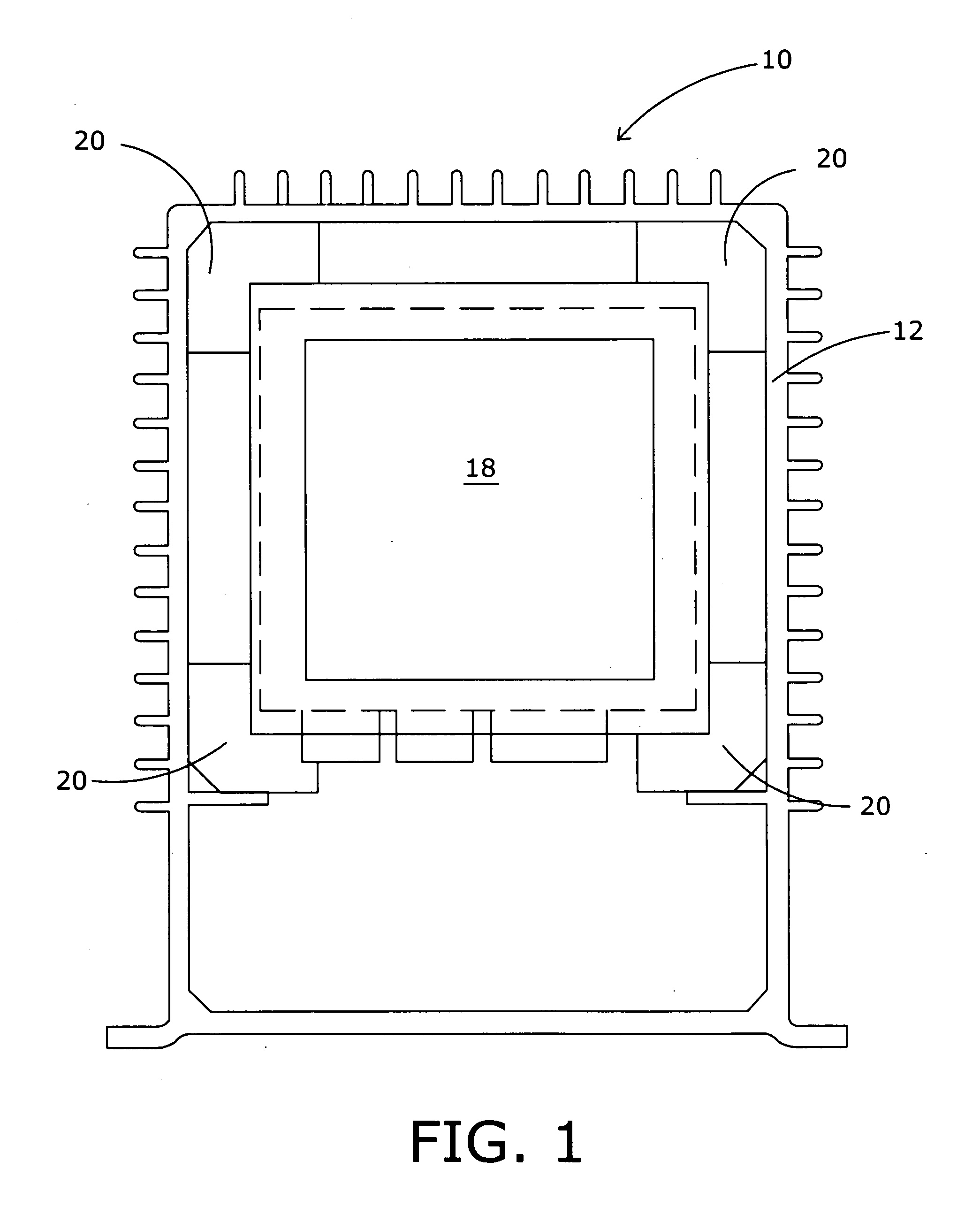
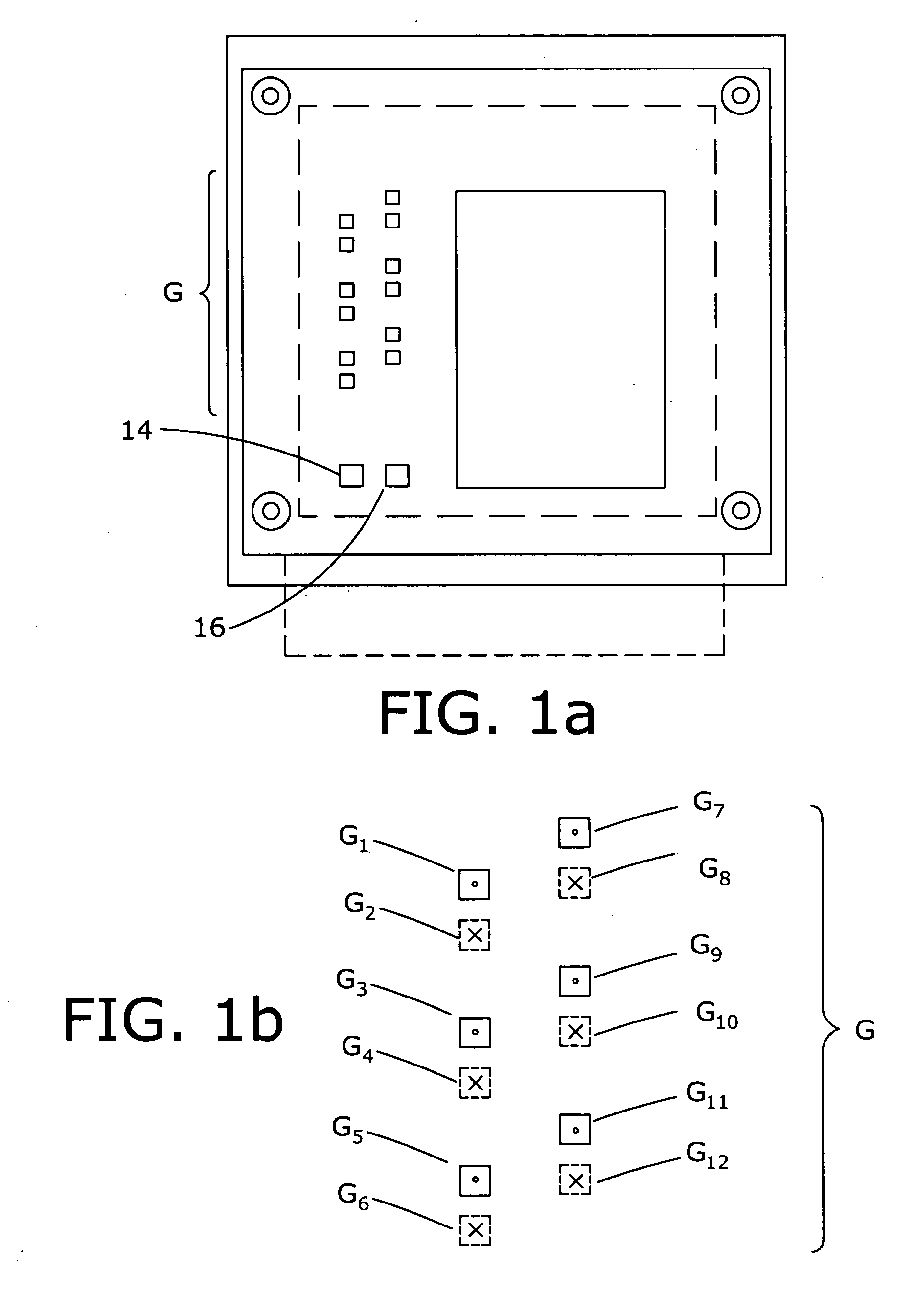
As second embodiment in accordance with the present invention is shown in FIG. 1c. As shown therein, the location determining system 10 includes a generally vertically aligned housing 12 that includes a rate gyro RG, a first accelerometer board 14′ and an orthogonally aligned second accelerometer board 16′. The various boards and devices are inter-connected by various cables and connectors (not specifically shown). As explained below, the rate gyro RG and the first accelerometer board 14 and the second accelerometer board 16 provide, respectively, rate of turn and three-axis acceleration information to the processing electronics.

A set of circuit card assemblies 18 is mounted in the upper portion of the housing 12; the circuit card assemblies 18 effects signal conditioning and processing as explained below. As in the case of the embodiment described above in FIGS. 1, 1a, 1b, and 1c, the circuit cards conform to the PC / 104 standard which provides for interconnectable circuit cards th...


PUM


Abstract

A locomotive location system and method utilizes inertial measurement inputs, including orthogonal acceleration inputs and turn rate information, in combination with wheel-mounted tachometer information and GPS/DGPS position fixes to provide processed outputs indicative of track occupancy, position, direction of travel, velocity, etc. Various navigation solutions are combined together to provide the desired information outputs using an optimal estimator designed specifically for rail applications and subjected to motion constraints reflecting the physical motion limitations of a locomotive. The system utilizes geo-reconciliation to minimize errors and solutions that identify track occupancy when traveling through a turnout.

Description

BACKGROUND OF THE INVENTION Various systems have been developed to track the movement of and location of railway trains on track systems. In its simplest form, train position can be ascertained at a central control facility by using information provided by the crew, i.e., the train crew periodically radios the train position to the central control facility; this technique diverts the attention of the crew while reporting the train position, often requires several “retries” where the radio link is intermittent, and the position information rapidly ages. Early efforts have involved trackside equipment to provide an indication of the location of a train in a trackway system. Wayside devices can include, for example, various types of electrical circuit completion switches or systems by which an electrical circuit is completed in response to the passage of a train. Since circuit completion switches or systems are typically separated by several miles, this technique provides a relative...

Claims


Application Information

Patent Timeline
IPC IPC(8): B61L25/02
CPCB61L25/021B61L25/023B61L2205/04B61L25/026B61L25/028B61L25/025
Inventor MEYER, THOMAS J.METZGER, THOMAS R.
Owner AUSTRALIAN RAIL TRACK CORP
Why Eureka
Try Eureka