
Hybrid scan-based delay testing technique for compact and high fault coverage test set

a delay testing and hybrid technology, applied in the direction of digital signal error detection/correction, instruments, recording signal processing, etc., can solve the problems of long design time, difficult application of hybrid scan-based delay testing techniques to standard scan designs, and often too costly to meet design requirements

Inactive Publication Date: 2005-03-24
NEC CORP
View PDF4 Cites 14 Cited by
  • Summary
  • Abstract
  • Description
  • Claims
  • Application Information

AI Technical Summary

Benefits of technology

It will be advantageous to have additional approaches that combine the advantages of the broad-side approach and the skewed-load approach.

Problems solved by technology

However, due to limited controllability of state inputs when standard scan is employed, applying these techniques to standard scan designs is not straightforward.
Such design requirement is often too costly to meet.
Furthermore, meeting such a strict timing required for the scan enable signal may result in longer design time.
Hence, if a state required to activate and propagate a fault is an invalid state, i.e., the state cannot be functionally justified, then the transition delay fault is untestable.
Due to this reason, transition fault coverage for standard scan designs is often substantially lower than stuck-at fault coverage.
However, since this technique requires enhanced scan cells, which can hold two bits, the disadvantage of enhanced scan testing is high area overhead of enhanced scan cells.
However, using the broad-side approach to avoid high hardware overhead will incur significantly higher test application cost and result in lower test quality for most designs than using the skewed-load approach.
As sizes and complexity of chips grow, size of test pattern sets also tend to grow.
Due to large test volume required to achieve satisfactory coverage, transition fault coverage is often compromised for acceptable test volume.

Method used


Image

  • Hybrid scan-based delay testing technique for compact and high fault coverage test set
  • Hybrid scan-based delay testing technique for compact and high fault coverage test set
  • Hybrid scan-based delay testing technique for compact and high fault coverage test set

Examples


Embodiment Construction

IV.A. Synopsis

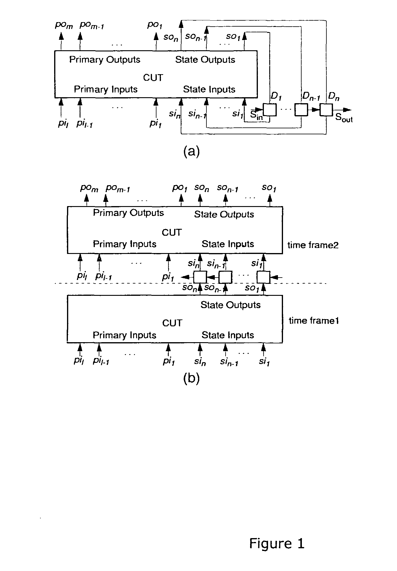
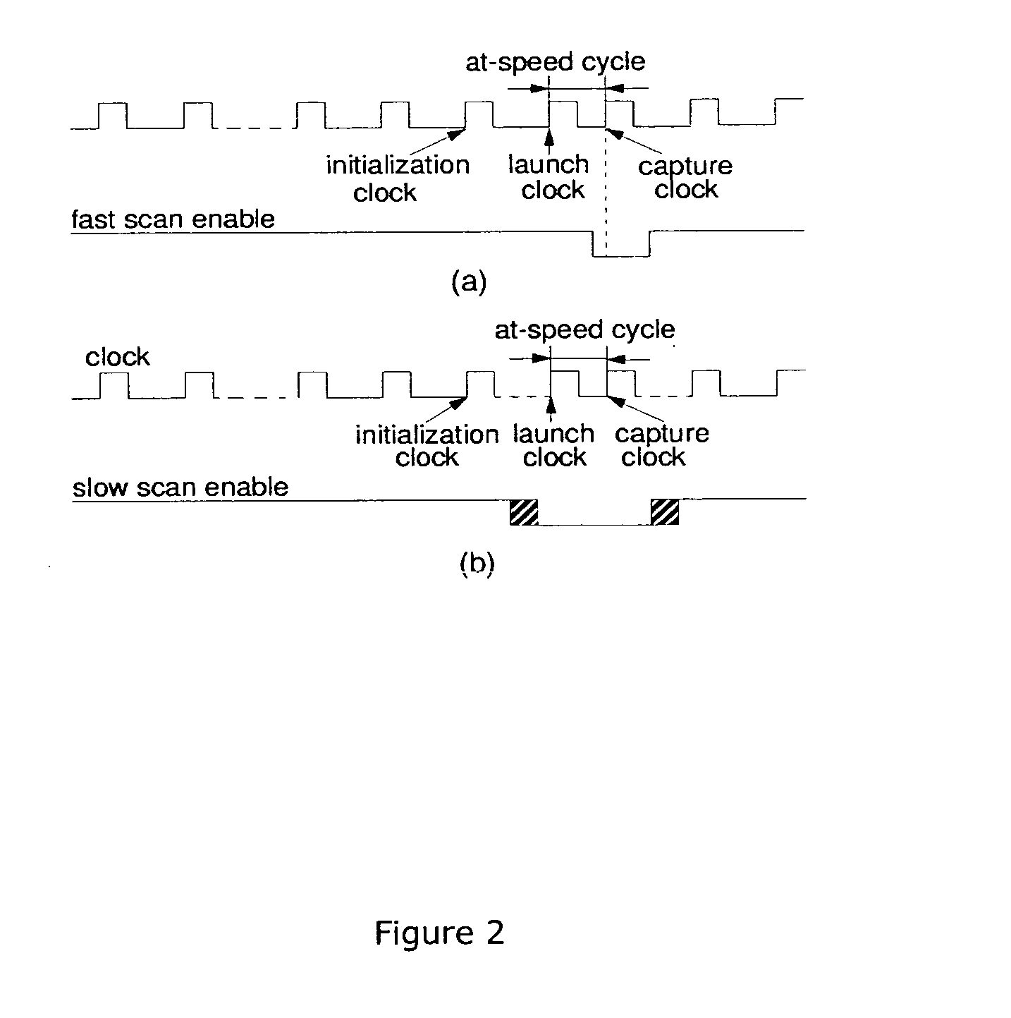
A novel scan-based delay test approach that combines advantages of the skewed-load and broad-side approaches are disclosed herein. In the hybrid approach, a subset of selected scan flip-flops are controlled by the skewed-load approach and the rest of scan flip-flops are controlled by the broad-side approach. It should be noted that the disclosed techniques are applicable to other delay fault models. For simplicity and ease of understanding, transition delay fault model is used as an example to illustrate the concepts of the disclosed teachings.

IV.B. Illustrative Example

Switching the scan enable signal that drives all scan flip-flops in a large circuit within one full system clock cycle requires a strong clock buffer or a buffer tree. But a scan enable signal that drives only a small number of flip-flops (say, 100 flip-flops) can switch in one full system clock cycle without any strong buffer or buffer tree. If only a small set of state inputs of the circuit requir...


PUM


Abstract

A scan-based method for testing delay faults in a circuit comprising controlling a subset of state inputs of the circuit by a skewed-load approach and controlling all inputs other than said subset of state inputs by a broad-side approach.

Description

I. DESCRIPTION I.A. Field The disclosed teachings relate to a hybrid scan-based delay testing technique that provides a high fault coverage test set. I.B. Background 1. References The following papers provide useful background information, for which they are incorporated herein by reference in their entirety, and are selectively referred to in the remainder of this disclosure by their accompanying reference keyword in square brackets (i.e., [CL95] for the by J.-S. Chang and C.-S. Lin.): [BRS+02] D. Belete, A. Razdan, W. Schwarz, R. Raina, C. Hawkins, and J. Morehead. Use of DFT Techniques In Speed Grading a 1 GHz+Microprocessor. In Proceedings IEEE International Test Conference, pages 1111-1119, 2002. [CIR87] J. L. Carter, V. S. Iyengar, and B. K. Rosen. Efficient Test Coverage Determination for Delay Faults. In Proceedings IEEE International Test Conference, pages 418-427, 1987. [CL95] J.-S. Chang and C.-S. Lin. Test Set Compaction for Combinational Circuits. In IEEE Trans....

Claims


Application Information

Patent Timeline
IPC IPC(8): G01R31/3185G06K5/04G11B5/00G11B20/18G11B20/20
CPCG11B20/1816G01R31/31858
Inventor WANG, SEONGMOONLIU, XIAOCHAKRADHAR, SRIMAT T.
Owner NEC CORP
Learn More