
System and method for correlated process pessimism removal for static timing analysis

Inactive Publication Date: 2005-03-24
GLOBALFOUNDRIES INC
View PDF8 Cites 64 Cited by
  • Summary
  • Abstract
  • Description
  • Claims
  • Application Information

AI Technical Summary

Benefits of technology

Accordingly, it is an object of the invention to provide a method for reducing the pessimism of bounded static timing analysis in the presence of variation caused by one or more sources of uncertainty.
These and other objects are achieved by a system and method that eliminates timing variations between signals traversing paths, and which are affected by the same sources of variation.

Problems solved by technology

For a setup constraint, if the minimum (or early) clock arrival time minus the maximum (or late) data arrival time is negative, the data may still become unstable following the occurrence of a clock transition, thus preventing the correct data from being stored in the storage element.
Similarly, for a hold constraint, if the minimum (or early) data arrival time minus the maximum (or late) clock arrival time is negative, the data may still become unstable before the occurrence of a clock transition, again preventing the correct data from being stored in the storage element.
In general, it is not possible to determine a priori which combination of parameter settings will produce the most critical timing.
Furthermore, delays may not be monotonic in all parameters, so that for different paths across a chip, different parameter assignments may be required to generate the latest (earliest) possible path delays.
For example, when considering variability in wire thickness, it is assumed that thin wires generally create the latest arrival time for wire-delay dominated paths due to increased wire resistance, whereas paths which are gate-delay dominated will typically exhibit longer delays when thick wiring is considered, due to increased wire capacitance loading of gates.
However, given the increasing number of independent parameters that have a significant impact on delay, such an approach is fast becoming impractical.
While this guarantees worst-case coverage (i.e., that all potential timing errors will be detected) without the need for multiple analyses, such an approach typically leads to overly pessimistic results since correlation is not properly accounted for.
If the design only contains a single power supply source, the assumption is deemed to be inconsistent and pessimistic since the circuits cannot operate simultaneously at two different power supply voltages (Note: this example ignores across-chip IR drop effects.)
The over-conservative nature of bounding techniques often precludes their practical use, forcing circuit designers to explicitly perform multiple analyses as described above.
However, the method described cannot remove pessimism due to paths that do not physically share the same cells, but which are dependent on the same underlying varying parameters.

Method used


Image

  • System and method for correlated process pessimism removal for static timing analysis
  • System and method for correlated process pessimism removal for static timing analysis
  • System and method for correlated process pessimism removal for static timing analysis

Examples


first embodiment

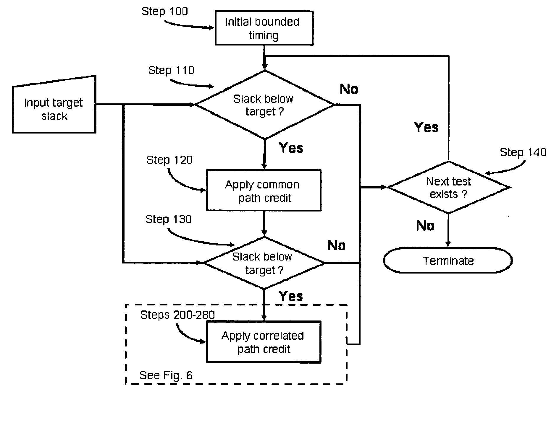
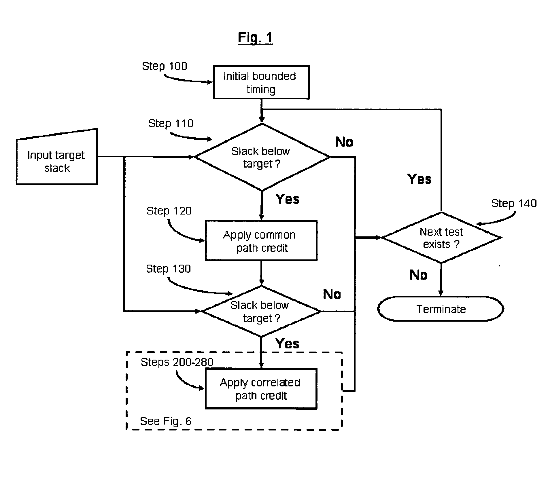
In the invention, the unique clock and data paths are re-analyzed for all combinations of common parameter settings.

In the illustrative circuit, the following eight parameter combinations are applied to the unique clock and data paths (BOX320, BOX330) and (BOX340, BOX350) 1. Xglobal_max, Yglobal_max, Zglobal_max 2. Xglobal_max, Yglobal_max, Zglobal_min 3. Xglobal_max, Yglobal_min, Zglobal_max 4. Xglobal_max, Yglobal_min, Zglobal_min 5. Xglobal_min, Yglobal_max, Zglobal_max 6. Xglobal_min, Yglobal_max, Zglobal_min 7. Xglobal_min, Yglobal_min, Zglobal_max 8. Xglobal_min, Yglobal_min, Zglobal_min

For parameters which are not common to both, the unique data and clock paths (in the illustrative circuit, W and V) are left in their initial bounding state.

For each of the aforementioned combinations, a new test slack is computed by propagating the original arrival times from the closest common clock / data point (in the illustrative circuit, it corresponds to BOX310) through the un...

second embodiment

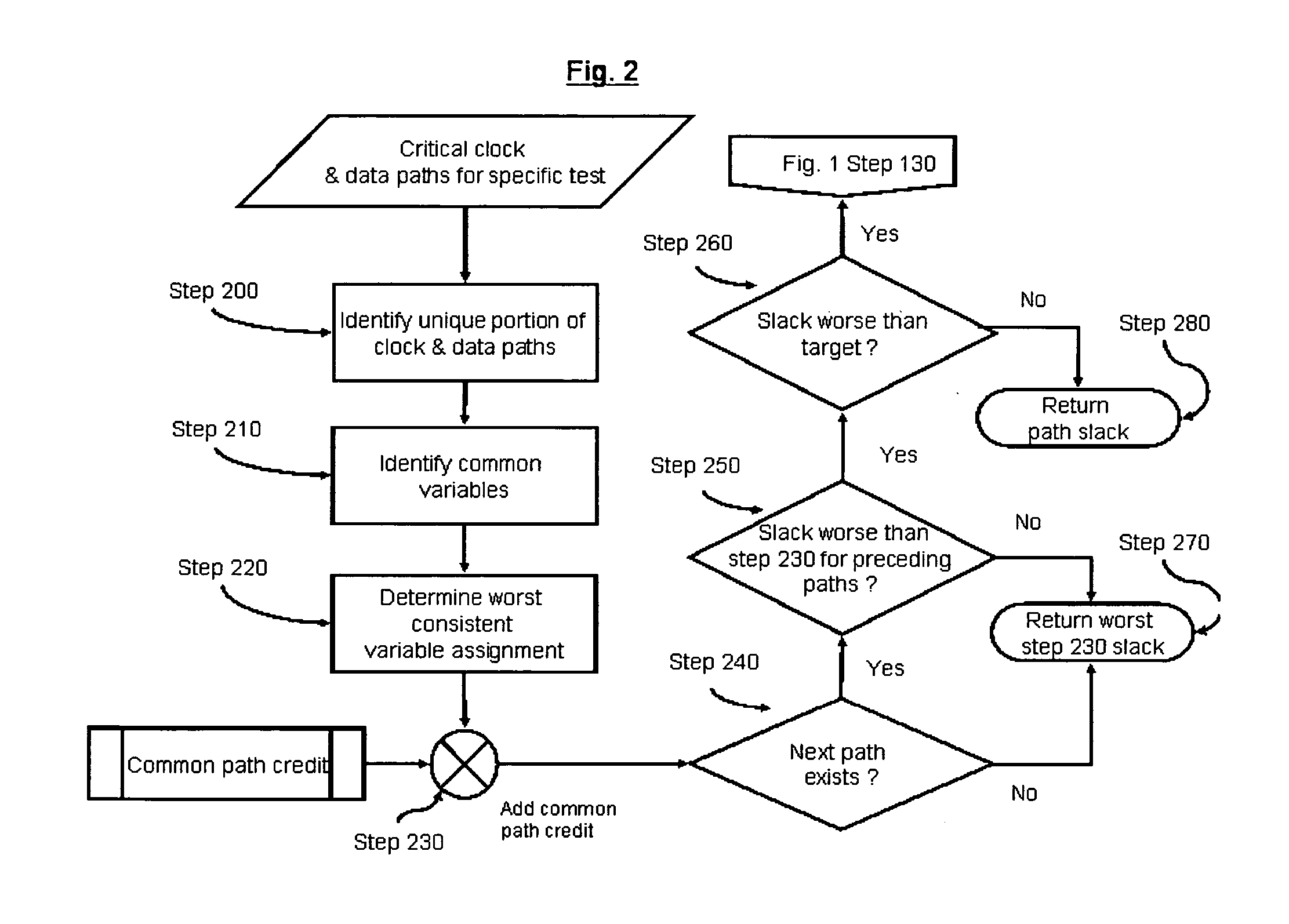
In the invention, consistent corners are selected for a limited set of parameters, e.g., those having the largest impact on delay, while the others remain in a bounded state. If the resulting slack is above the target slack, no further exploration of parameter combinations for the current path-pair is required; otherwise, additional variables may be successively explored until the slack threshold is met.

In the illustrative circuit, for the first critical data path, an initial expansion for parameter X considers the following combinations: Data path: Xglobal_min, Yglobal_max, Zglobal_max versus Clock path: Xglobal_min, Yglobal_min, Zglobal_min Data path: Xglobal_max, Yglobal_max, Zglobal_max versus Clock path: Xglobal_max, Yglobal_min, Zglobal_min

The Xglobal_min combination resulting in a non-negative slack is computed as follows:

((15+15+30)−(30+30+15))=−15

Slack including common path credit=−15+15=0

Since this slack meets the specified threshold ‘0’, no further analysis o...

third embodiment

In the invention, parameters that have a separable impact on delay are projected independently to a worst-case corner. Linear complexity per path is guaranteed for the variables which are separable, unlike previous embodiments, wherein exponential complexity is still possible in the worst case (i.e., if each parameter expansion produces a slack below the specified cutoff).

For the critical data and clock paths in the illustrative circuit, parameter X is assigned a value based on the worst slack among: Xglobal_max (all other parameters bounded) Data path: Xglobal_max, Yglobal_max, Zglobal_max Clock path: Xglobal_max, Yglobal_min, Zglobal_min

Slack=((15+20+30)−(30+40+15))=−20 and Xglobal_min (all other parameters bounded) Data path: Xglobal_min, Yglobal_max, Zglobal_max Clock path: Xglobal_min, Yglobal_min, Zglobal_min

Slack=((15+15+30)−(30+30+15))=−15

In the present example, a consistent assignment of Xglobal_max generates the worst slack. Parameter Y is then assigned a value...


PUM


Abstract

A method of removing pessimism in static timing analysis is described. Delays are expressed as a function of discrete parameter settings allowing for both local and global variation to be taken in to account. Based on a specified target slack, each failing timing test is examined to determine a consistent set of parameter settings which produces the worst possible slack. The analysis is performed on a path basis. By considering only parameters which are in common to a particular data / clock path-pair, the number of process combinations that need to be explored is reduced when compared to analyzing all combinations of the global parameter settings. Further, if parameters are separable and linear, worst-case variable assignments for a particular clock / data path pair can be computed in linear time by independently assigning each parameter value. In addition, if available, the incremental delay change with respect to each physically realizable process variable may be used to project the worst-case variable assignment on a per-path basis without the need for performing explicit corner enumeration.

Description

BACKGROUND OF THE INVENTION The invention is related to the field of Electronic Design Automation, and more specifically, to a method of reducing pessimism in static timing analysis when considering variation effects on the circuit delay. Static timing is used widely in order to verify the timing of digital integrated circuit designs by calculating delays and propagating signal arrival times to determine the interval in which signals will be stable within a single clock cycle. In particular, for internal storage elements, the latest (earliest) arrival time data propagated along a data path is compared against the earliest (latest) arrival time propagated along a clock path to identify potential setup (hold) violations. The difference between the data and clock path arrival times, including the setup or hold time of the sequential element is referred to as ‘slack.’ This difference is computed so that a negative slack value signals a timing violation. For a setup constraint, if the ...

Claims


Application Information

Patent Timeline
IPC IPC(8): G06F9/45G06F17/50
CPCG06F17/5031G06F30/3312
Inventor KALAFALA, KERIMQI, PEIHUAHATHAWAY, DAVID J.SUESS, ALEXANDER J.VISWESWARIAH, CHANDRAMOULI
Owner GLOBALFOUNDRIES INC
Learn More