Stator core, an electric motor in which it is utilized, and method of manufacturing a stator core

a stator core and electric motor technology, applied in the field of stator cores, can solve the problems of increasing the production cost of the core, the shorter die, the increase in the maintenance cost of the manufacturing facility, etc., and achieves the effects of reducing the production cost of the stator core, increasing the life of the cutting die, and preventing the portion from falling o

Active Publication Date: 2005-03-31
NIDEC SHIBAURA CORP
View PDF8 Cites 68 Cited by
  • Summary
  • Abstract
  • Description
  • Claims
  • Application Information

AI Technical Summary

Benefits of technology

[0015] In one aspect of the present invention, a stator core reducing the production cost of a stator core by increasing the life time of a cutting die for manufacturing stator cores is provided. In one embodiment, the stator core is formed by laminated straight cores including a plurality of teeth portions, bent portions being provided with V-shaped notches, which define V-shaped gaps opened to one direction and interposing between each of the teeth portions. The straight cores are formed into an annular configuration by bending

Problems solved by technology

Therefore, the depreciation and repair costs of the cutting dies and the maintenance of manufacturing facilities are increased, because partial abrasion loss of the cutting dies become larger and duration of the cutting dies become shorter.
Which

Method used


Image

  • Stator core, an electric motor in which it is utilized, and method of manufacturing a stator core
  • Stator core, an electric motor in which it is utilized, and method of manufacturing a stator core
  • Stator core, an electric motor in which it is utilized, and method of manufacturing a stator core

Examples


first embodiment

[0035] First Embodiment

[0036] Referring now to FIGS. 1 through 7, a preferred first embodiment of the present invention will be described in detail.

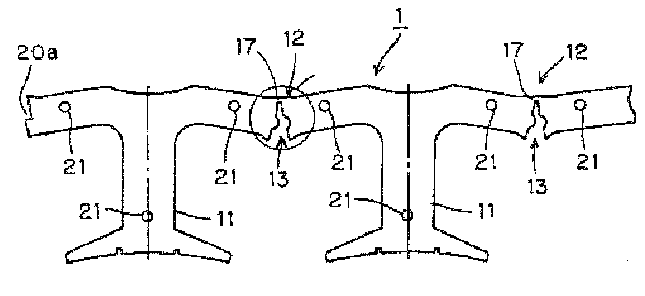
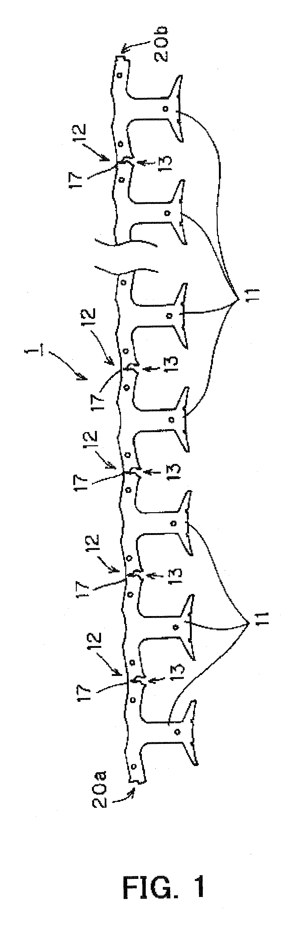
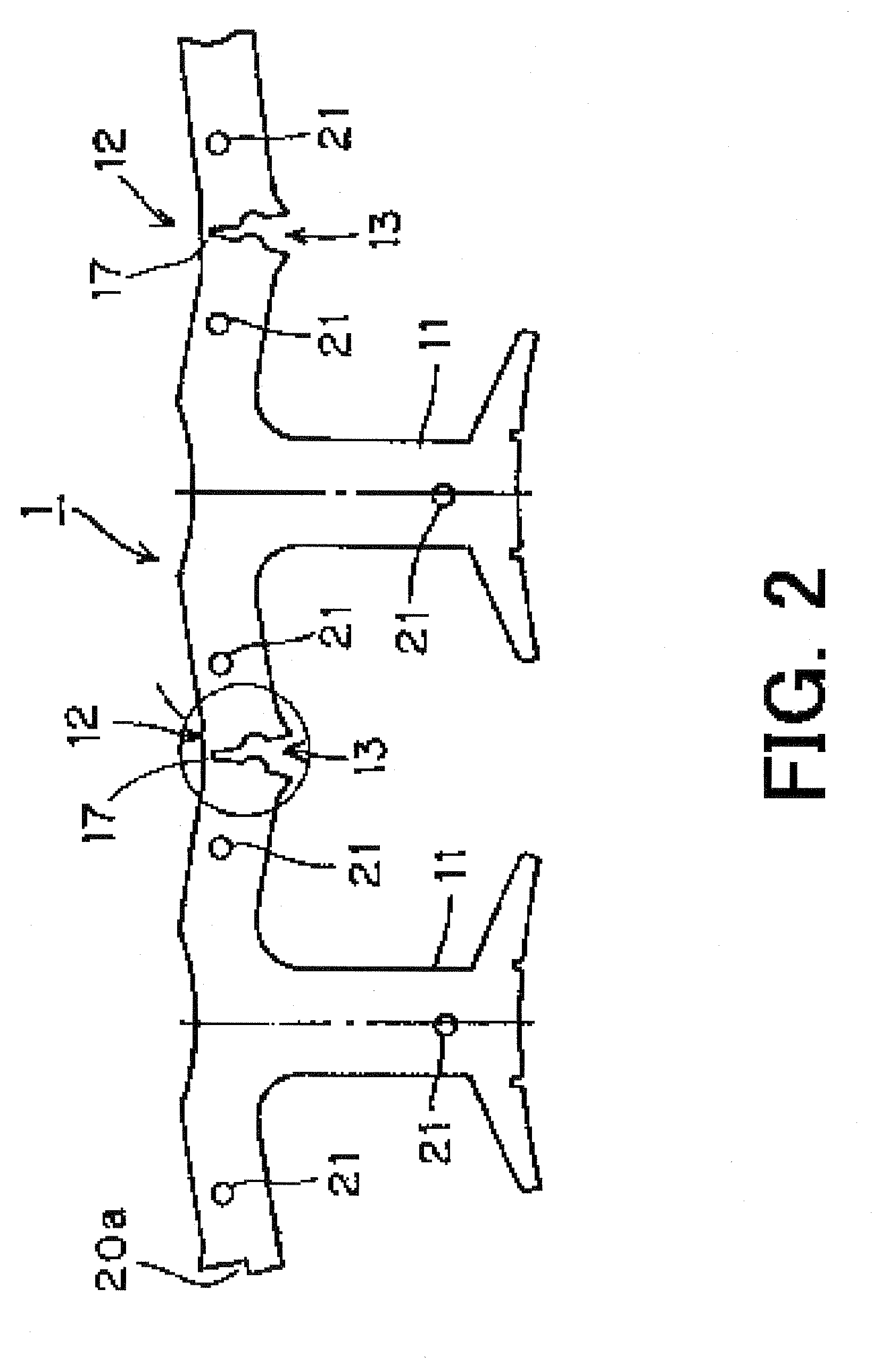
[0037]FIG. 1 is a plan view showing a straight core 1 forming a stator core of an electric motor. FIG. 2 is an enlarge fragmentary sectional view showing the straight core 1 depicted in FIG. 1, and FIG. 3 is an enlarge fragmentary schematic view showing a V-shaped notch being provided at a bent portion (section A of FIG. 2).

[0038] A straight core 1 shown in FIGS. 1 and 2 is made by punching laminated silicon steel sheets and manufactured by a pressing machine using cutting dies. The straight core 1 includes a plurality of T-shaped teeth portions 11 having a core back portion and a tooth extending from the core back portion. V-shaped notches 13, which define V-shaped gaps opened to one direction, are formed between the teeth portions 11 and each of the teeth portions 11 are connected with each other via thin portions 17 which are integr...

second embodiment

[0053] Second Embodiment

[0054]FIG. 8 shows a plan view of segment core elements30 for forming a stator core of a second embodiment of the present invention. The segment core elements 30 are composed of plural independent segment cores 31 formed by cutting off each of teeth portions 32 at bent portions 33 and aligning the segment cores 31.

[0055] A laminated core 4 shown in FIG. 9 is formed by alternate lamination of the straight core 1 of the first embodiment and the segment core elements 30 so as to overlap the teeth portions 11 of the straight core 1 and the teeth portions 32 of the segment core elements 30. As shown in FIG. 9 depicting a side view of the laminated core 4, lengthwise slits 35 are formed between bounded segment cores 31 and 31 at the bent portions 33 of the laminated core 4 and thin portions and the slits 35 are alternatively disposed between the teeth portions of the laminated core 4.

[0056] In the second embodiment of the present invention, the slits 35 forms par...


PUM

PropertyMeasurementUnit
Bending strengthaaaaaaaaaa
Deformation enthalpyaaaaaaaaaa

Abstract

In a stator core is formed by laminated strip-shaped straight cores including a plurality of teeth portions, bent portions being provided with V-shaped notches, which define V-shaped gaps opened to one direction and interposing between each of the teeth portions, the straight cores being formed into an annular configuration by bending the bent portions in a direction so as to close the V-shaped notches and circular holes being provided at the bent portions so as to form a series of gaps between each of the teeth portions. The straight cores further include deformation preventing portions formed on the bent portions by cutting off a part of a pair of oblique lines defining the V-shaped notches toward the circular holes so as to expand the gaps of the V-shaped notches and the circular holes for preventing the bent portions from deforming by stress of bending process.

Description

BACKGROUND OF INVENTION [0001] 1. Technical Field [0002] The present invention relates to a stator core which can be used in an electric motor such as a brushless DC motor and a method of manufacturing thereof. [0003] 2. Description of the Related Art [0004] A stator core is generally formed by bending an elongate and straight strip made of thin silicon steel into an annular shape, and by making a lamination with a plurality of the bent strips. In this specification, such straight strip is referred to as “straight core”. Each straight core is made by punching laminated wide and thin silicon steel sheets. The straight core includes a plurality of teeth portions, each of which has a T-shape, and a plurality of core back portions, each of which connects two T-shaped teeth portions next to each other. [0005] To explain a conventional straight core, a partial plan view of an unbent straight core is shown in FIG. 10. The conventional straight core 100 is made by punching laminated silicon...

Claims


Application Information

Patent Timeline
IPC IPC(8): H02K1/14
CPCY10T29/49009H02K1/148
Inventor MURAKAMI, TAKUYAMURAKAMI, TOSHIAKI
Owner NIDEC SHIBAURA CORP
Why Eureka
Try Eureka