Magneto-generator
- Summary
- Abstract
- Description
- Claims
- Application Information
AI Technical Summary
Benefits of technology
Problems solved by technology
Method used
Image

Examples
embodiment 1
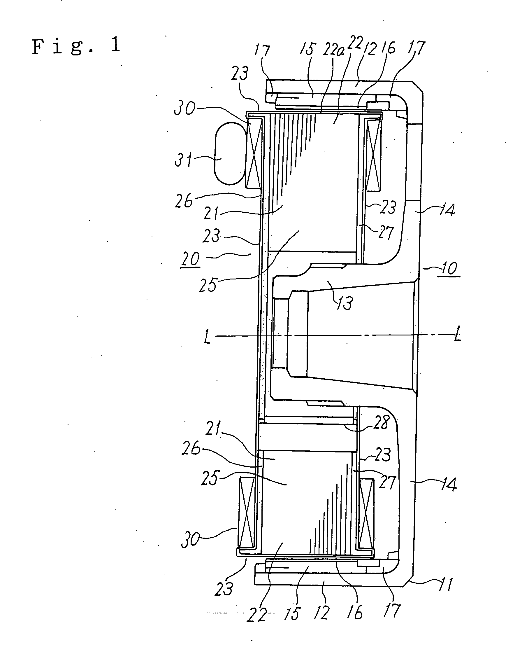
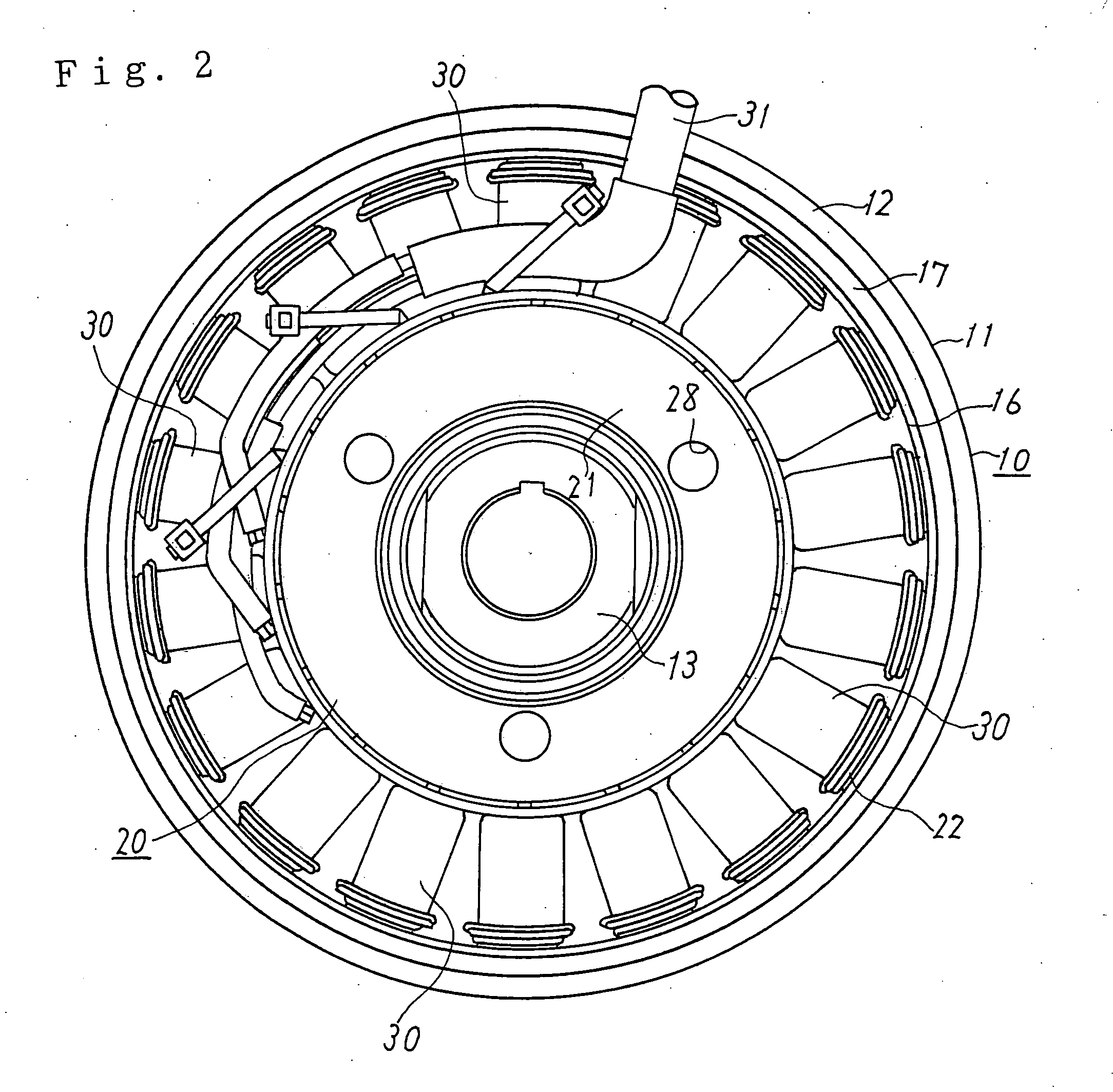
[0019]FIG. 1 is a vertical sectional view of a magneto-generator according to the first embodiment of the invention, and FIG. 2 is its left-hand side.
[0020] The magneto-generator according to the first embodiment is a flywheel magneto-generator which is mounted on a two-wheeled vehicle, an outboard machine, a snowmobile, or the like and is used for charging a battery, supplying power to various loads, and other purposes when driven by its internal combustion engine or the like.
[0021] The flywheel magneto-generator according to the first embodiment is equipped with a rotor 10 and a stator 20.
[0022] The rotor 10 has a bowl-shaped flywheel 11, which includes an outer cylindrical portion 12, an inner boss portion 13, and a bottom portion 14 that connects the cylindrical portion 12 and the boss portion 13. The flywheel 11 rotates about a rotation axis L-L. The boss portion 13 is fixed to a rotary shaft that is driven by an internal combustion engine (not shown).
[0023] A plurality of ...
embodiment 2
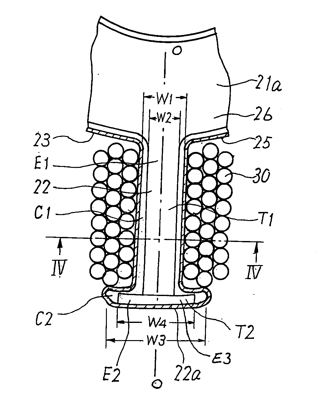
[0041]FIG. 6 shows a flywheel magneto-generator according to a second embodiment of the invention. FIG. 6 is a vertical sectional view of an upper half (above the rotation axis L-L) of the flywheel magneto-generator according to the second embodiment. In the second embodiment, the first portion El of each of the end plates 26 and 27 is made of a magnetic metal material such as cold-rolled steel and the second portion E2 and the projection E3 are made of a non-magnetic metal material such as stainless steel (SUS 304). The second portion E2 having the projection E3 is fixed to the outer end of the first portion E1 by welding, for example. Although the insulating film 23 is omitted in FIG. 6, the outer surfaces of the teeth 22 are coated with the insulating film 23 as in the case of the first embodiment. The second embodiment is the same as the first embodiment in the other part of the configuration.
[0042] In the second embodiment, as in the first embodiment, the circumferential width...
embodiment 3
[0043]FIG. 7 shows a flywheel magneto-generator according to a third embodiment of the invention. FIG. 7 is a vertical sectional view of an upper half (above the rotation axis L-L) of the flywheel magneto-generator according to the third embodiment. In the third embodiment, the end plates 26 and 27 are made of different non-magnetic metal materials. More specifically, the first portion E1, the second portion E2, and the projection E3 of the end plate 26 are made of one non-magnetic metal material such as aluminum and those of the end plate 27 are made of another non-magnetic metal material such as stainless steel (SUS 304). Since aluminum is less rigid than stainless steel, the end plate 26 is made thicker than the end plate 27 so as to have approximately the same degree of rigidity as the latter. An aluminum plate can be shaped more easily than a stainless steel plate. Although the insulating film 23 is omitted in FIG. 7, the outer surfaces of the teeth 22 are coated with the insul...
PUM
 Abstract
Description
Claims
Application Information
 - R&D
- Intellectual Property
- Life Sciences
- Materials
- Tech Scout
- Unparalleled Data Quality
- Higher Quality Content
- 60% Fewer Hallucinations
Browse by: Latest US Patents, China's latest patents, Technical Efficacy Thesaurus, Application Domain, Technology Topic, Popular Technical Reports.
© 2025 PatSnap. All rights reserved.Legal|Privacy policy|Modern Slavery Act Transparency Statement|Sitemap|About US| Contact US: help@patsnap.com