Organic EL element and organic EL panel

a technology of organic el and organic el, which is applied in the direction of discharge tube luminescnet screen, identification means, instruments, etc., can solve the problems of difficult and complex panel manufacturing process, insufficient emissivity efficiency for each color, and uneven color generation within displayed colors, so as to overcome the disadvantage of using microresonators and eliminate the negative influence of insufficient optical selectivity of microresonators

Active Publication Date: 2005-03-31
SANYO ELECTRIC CO LTD
View PDF16 Cites 68 Cited by
  • Summary
  • Abstract
  • Description
  • Claims
  • Application Information

AI Technical Summary

Benefits of technology

[0011] An advantage of the present invention is that negative influences from insufficient optical selectivity of microresonators can be eliminated.
[0012] According to the present invention, a light-shielding

Problems solved by technology

However, when employing this method, the panel manufacturing process becomes difficult and complex because measures must be effected to compensate for differences in emissive efficiency of the emissive materials for different colors, and steps for applying different emissive materials to corresponding pixels must be carried out separately.
However, according to these methods, it is difficult to achieve

Method used


Image

  • Organic EL element and organic EL panel
  • Organic EL element and organic EL panel
  • Organic EL element and organic EL panel

Examples


Embodiment Construction

[0018] Preferred embodiments of the present invention will next be described referring to the drawings.

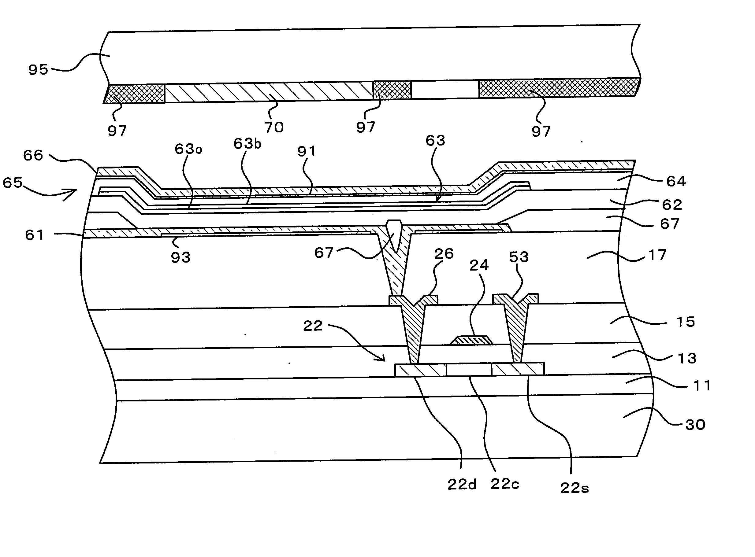
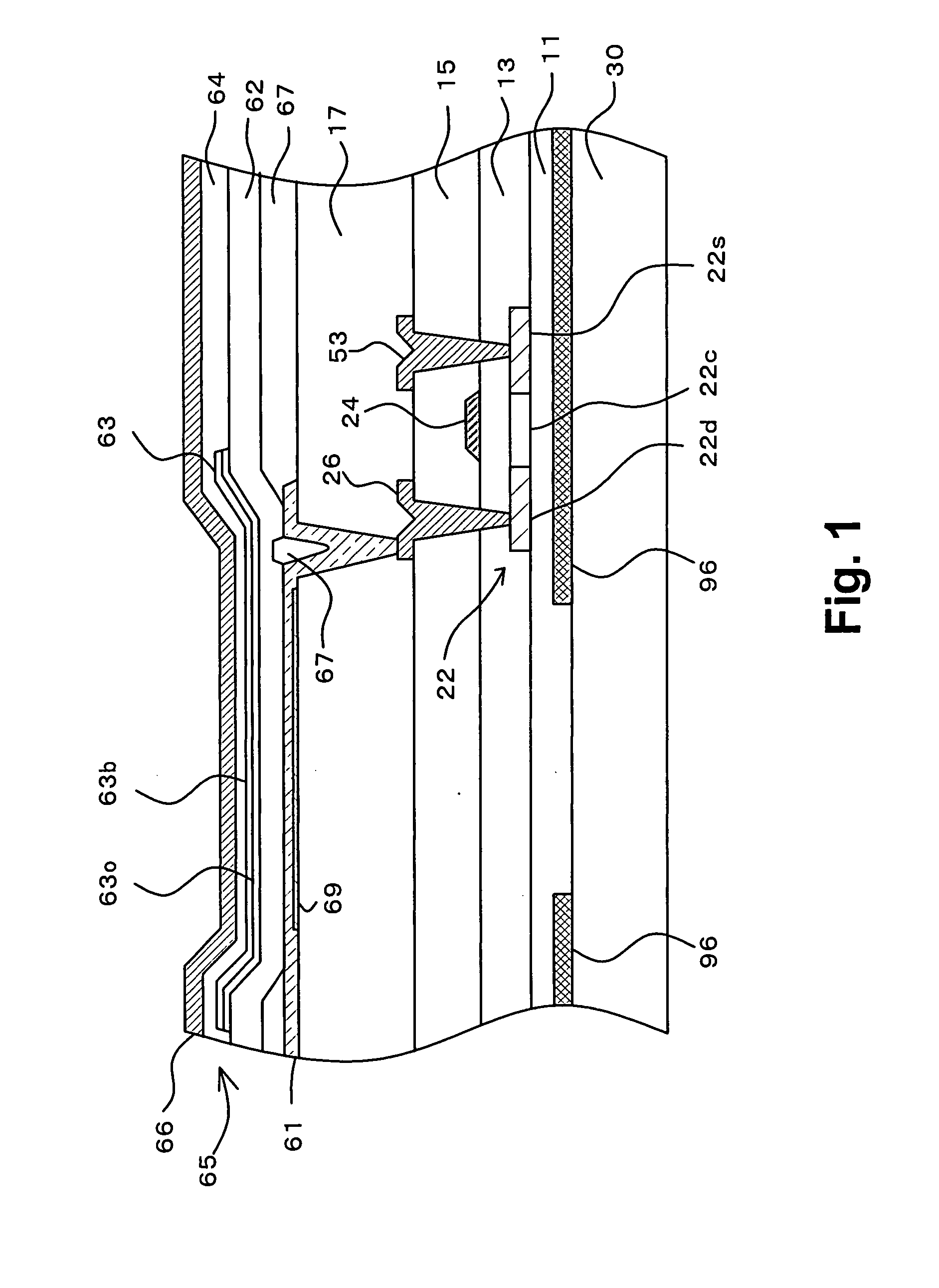
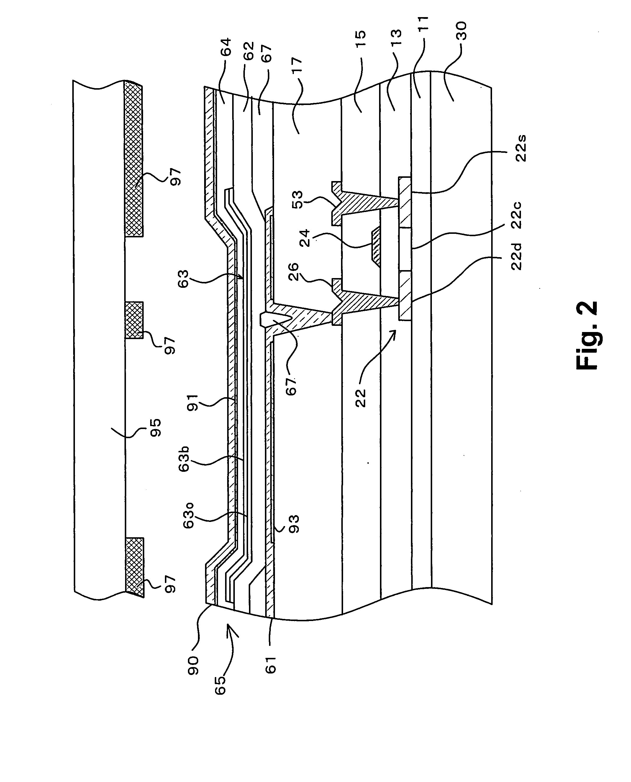
[0019]FIG. 1 is a cross-sectional view showing a configuration of a light-emitting region and a drive TFT (thin film transistor) within one pixel. It should be noted that each pixel actually includes a plurality of TFTs. The drive TFT is the TFT which controls a current supplied from a power line to an organic EL element within the pixel.

[0020] On a glass substrate 30, a light-shielding film 96 is formed to cover the peripheral portion of the light-emitting region. The light-shielding film 96 may be composed of various materials such as those used for a black matrix in an LCD. Examples of materials that can be used for the light-shielding film 96 include a black material formed of chromium, a resist obtained by mixing a black pigment or dye in a resist (photosensitive resin), and a resin material obtained by dispersing a black pigment in a polymer.

[0021] Covering the glass subst...


PUM


Abstract

A semi-transmissive film is provided underneath a transparent electrode of an organic EL element. The optical length of the interval between the upper surface of the semi-transmissive film and the lower surface of a counter electrode serving as a reflective layer is configured such that this interval functions as a microresonator for selecting light having a specific wavelength. Further, a light-shielding film is provided in a position corresponding to the peripheral portion of the semi-transmissive film, so as to prevent light having a different color from being ejected due to non-uniformity in the optical length.

Description

CROSS-REFERENCE TO RELATED APPLICATIONS [0001] The priority Japanese application No. 2003-342663 upon which this patent application is based is hereby incorporated by reference. BACKGROUND OF THE INVENTION [0002] 1. Field of the Invention [0003] The present invention relates to an organic EL element which comprises a transparent electrode, an organic emissive layer disposed over the transparent electrode, and a counter electrode disposed over the organic emissive layer, and emits light when a voltage is applied between the transparent electrode and the counter electrode. [0004] 2. Description of the Related Art [0005] In recent years, organic electroluminescence (hereinafter referred to as “EL”) displays have gained attention as one type of flat display which would replace liquid crystal displays in the coming generation. In a display panel of an organic EL display (hereinafter referred to as “organic EL panel”), the color of light emitted from each pixel may be determined depending...

Claims


Application Information

Patent Timeline
IPC IPC(8): G09F9/30H05B33/24H01L27/32H01L51/50H01L51/52H05B33/00H05B33/02H05B33/12H05B33/14H05B33/22H05B33/26H05B33/28
CPCH01L27/3206H01L27/322H01L27/3244H01L27/3272H01L51/5036H01L2251/5315H01L51/5218H01L51/5234H01L51/5265H01L51/5284H01L51/5215H10K59/30H10K59/38H10K59/123H10K59/126H10K59/12H10K50/125H10K50/816H10K50/818H10K50/828H10K50/852H10K50/865H10K2102/3026H05B33/22
Inventor NISHIKAWA, RYUJIOMURA, TETSUJI
Owner SANYO ELECTRIC CO LTD
Why Eureka
Try Eureka