Pointing device

a pointing device and pointing technology, applied in the direction of mechanical control devices, instruments, manual control with single controlling member, etc., can solve the problems of deterioration of the operability of the entire assembly process of the information apparatus, difficulty in etc., to achieve the effect of reducing the outside dimension of the pointing device and not deteriorating the operability of the operating section

Inactive Publication Date: 2005-03-31
FUJITSU COMPONENENT LTD
View PDF81 Cites 23 Cited by
  • Summary
  • Abstract
  • Description
  • Claims
  • Application Information

AI Technical Summary

Benefits of technology

[0011] It is therefore an object of the present invention to provide a pointing device with a magneto-electro transducer, capable of reducing an outside dimension of the pointing device to such a degree as to permit the pointing device to be installed into a portable information apparatus, without deteriorating the operability of an operating section.

Problems solved by technology

As a result, it has been difficult to reduce an outside dimension of the pointing device to such a degree as to permit the pointing device to be installed into a portable information apparatus.
Furthermore, in the case where the pointing device with the magneto-electro transducer is installed into a portable information apparatus, various miniaturized components of the pointing device may make the handling thereof troublesome, and thereby the operability of the entire assembling process of the information apparatus may be deteriorated.

Method used


Image

  • Pointing device
  • Pointing device
  • Pointing device

Examples


first embodiment

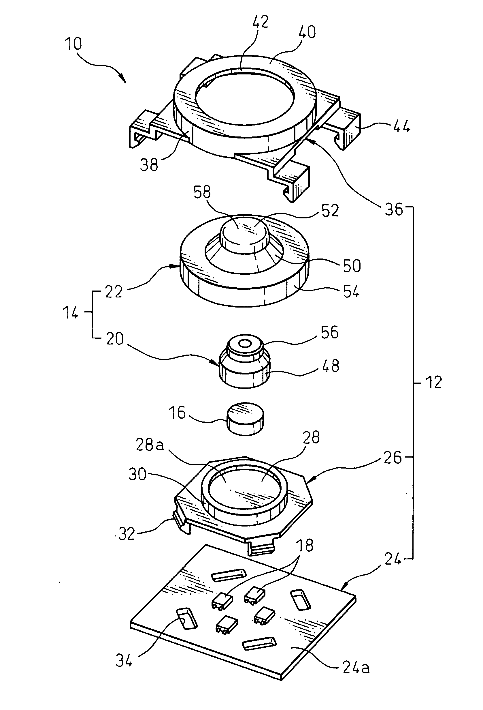
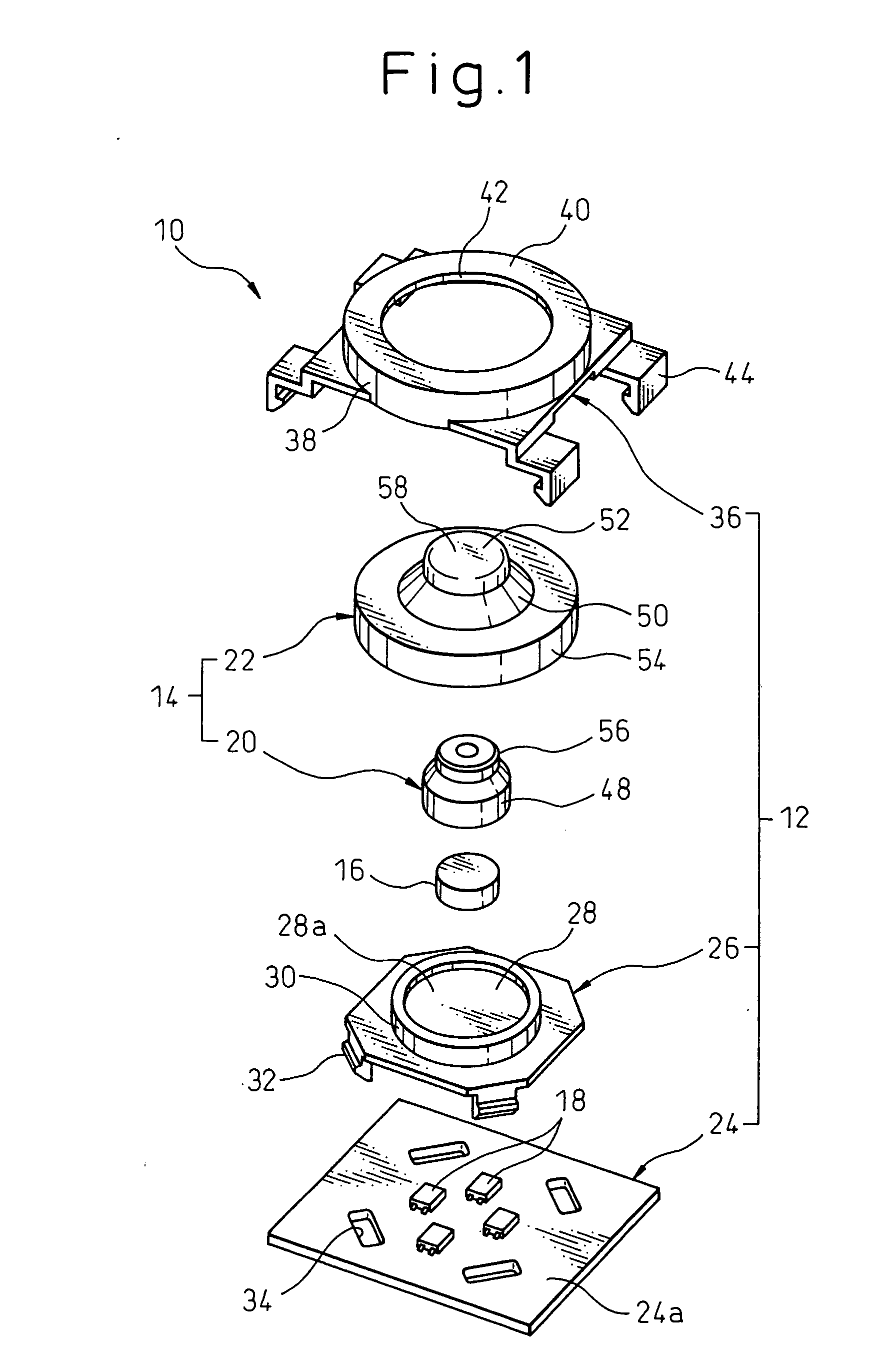
[0134] Referring now to the drawings, in which the same or similar components are denoted by common reference numerals, FIG. 1 shows a pointing device 10, according to the present invention, in an exploded perspective view, FIG. 2 shows the pointing device 10 in an assembled perspective view, and FIG. 3 shows the pointing device 10 in a vertical sectional view in the assembled state. The pointing device 10 is capable of being used in various data processors, such as personal computers, word processors, etc., as well as various portable information apparatuses, such as electronic notebooks, personal digital assistants (PDAs), mobile phones, etc., as an auxiliary input device for directing two-dimensional coordinate data on a display screen, and capable of being integrally incorporated in a casing of such a data processor or a portable information apparatus.

[0135] The pointing device 10 includes a base section 12, an operating section 14 supported on the base section 12 and shiftable ...

eighth embodiment

[0252]FIGS. 45A and 45B show a circuit board 340 and a key panel 342, as components of a portable information apparatus, such as a mobile phone, according to one embodiment of the invention. This portable information apparatus includes the pointing device 260 as the above-described eighth embodiment, installed with a characteristic structure for improving the operability of the assembling process, and thus corresponding components are denoted by the common reference numerals and an explanation thereof is not repeated.

[0253] As shown in FIG. 45A, the circuit board 340 is provided on the surface 340a thereof with a plurality of switches 344, as a main input section of the information apparatus, installed in a predetermined ordered arrangement. The circuit board 340 is also provided at predetermined positions on the surface 340a with a plurality (four, in the drawing) of arcuate slots 346 for fittings of the elastic part 202 of the pointing device 260. The slots 346 respectively corres...

tenth embodiment

[0266] Further, in the above structure, it is possible, as shown in FIG. 51, to define a certain space between the surface 360a of the circuit board 360 and the support member 26 in the housing 364, which advantageously increases a mounting area for electronic parts on the circuit board 360. It will be appreciated that, in the case where a switch mechanism for a click function is added to the pointing device 366 in the above structure, the support member 314 having the elastic beams 316 in the pointing device 310 may be integrally formed with the housing 364, as shown in FIG. 52, instead of the support member 26.

[0267] FIGS. 53 to 55 show a lower panel 380, a membrane sheet 382, a switch panel 384 and a key top 386, as components of a portable information apparatus, such as a mobile phone, according to a further embodiment of the invention. This portable information apparatus includes a pointing device 388 similar to the pointing device 10 as the above-described first embodiment, i...


PUM

PropertyMeasurementUnit
elastic forceaaaaaaaaaa
elasticaaaaaaaaaa
output voltageaaaaaaaaaa

Abstract

A pointing device including a base section, an operating section shiftably supported on the base section, a magnet carried on one of the base section and the operating section, and a magneto-electro transducer carried on the other of the base section and the operating section at a location close to the magnet. The operating section includes a first part securely holding one of the magnet and the magneto-electro transducer and supported on the base section shiftably in a desired horizontal direction relative to the base section, and a second part connected to the first part and elastically biasing the first part toward a home position in a horizontal shifting range during a period when the first part is horizontally shifted along the base section. The second part of the operating section is provided integrally with a major portion substantially surrounding an entire circumference of the first part, a first connecting portion connected to the first part at one end of the major portion and a second connecting portion connected to the base section at another end of the major portion; the major portion exerting an even elastic biasing force irrespective of a shifting direction of the first part on the base section.

Description

BACKGROUND OF THE INVENTION [0001] 1. Field of the Invention [0002] The present invention relates, generally, to an input device for electronic equipment and, more particularly, to a pointing device capable of being installed in data processors. The present invention also relates to a portable information apparatus incorporating therein a pointing device. The present invention further relates to a method of manufacturing an assembly of a circuit board and a connector, which may be provided in electronic equipment such as a pointing device. [0003] 2. Description of the Related Art [0004] It is well known that, in digital data processors with displays and keyboards, such as personal computers, word processors, personal digital assistants (PDAs), etc., a pointing device as an auxiliary input device for enabling an operator to manually enter analogue-type information so as to direct two-dimensional coordinate data, such as cursor shifting data, on a display screen is incorporated. Parti...

Claims


Application Information

Patent Timeline
Patent Type & Authority Applications(United States)
IPC IPC(8): G01L5/16G06F3/038G05G9/047G06F3/033G06F3/0338
CPCG05G9/047G05G2009/04744G06F3/0338G05G2009/04777G05G2009/04755
Inventor NISHINO, TAKESHINAKAMURA, SHUJIKIRYU, KOICHIKOBAYASHI, KAZUO
Owner FUJITSU COMPONENENT LTD
Why Eureka
Try Eureka