Modular inductor for use in power electronic circuits

a technology of power electronic circuits and modules, applied in the direction of electric variable regulation, process and machine control, instruments, etc., can solve the problems of large heat generation, physical packaging in such applications becomes problematic, and thermal management becomes extremely problematic, so as to improve thermal management, improve thermal gradient, and expand the effect of the footprin

Inactive Publication Date: 2005-03-31
ROCKWELL AUTOMATION TECH
View PDF12 Cites 32 Cited by
  • Summary
  • Abstract
  • Description
  • Claims
  • Application Information

AI Technical Summary

Benefits of technology

[0007] The present invention provides an inductor configuration designed to respond to such needs. The technique employs a modular inductor which can establish an improved thermal gradient so as to drive cooling of internal regions into a desired thermal range during operation. The package preferably includes an expanded footprint as compared to heretofore known structures, thereby providing a greater surface through which heat may be transferred. The modular package may include leads that extend from the inductor conductive elements for simple and straightforward incorporation with other modular components in various circuit designs. The modular package may include or may be adapted for inclusion with a thermal base, such as a liquid-cooled mounting surface or support. Such surfaces may be provided on one or multiple sides of the inductor structures so as to further enhance the thermal performance.
[0008] In accordance with certain aspects of the technique, various additional circuit components may be incorporated into the inductor package. These may include, where desired, inductors of different configuration, capacitor circuits, sensing circuits, and so forth. The integrated nature of such components within the inductor package further enhances the utility of the inductor, while providing a compact modular arrangement that can be easily cooled during operation along with the inductor coil.
[0009] In certain configurations, the inductor assembly may include multiple separate inductors that are arranged in a single modular structure. The inductor assembly may thus be adapted for three phase applications, such as in power converter circuits. Such power converter circuits are also envisaged by the invention, with the modularity of the inductor packaging and improved cooling further facilitating construction of a compact, high performance system in conjunction with active and passive switching circuits, such as inverters, filters, and so forth.
[0010] By virtue of the packaging techniques offered by the present invention, the invention also offers novel circuit and hardware configurations. Accordingly, the technique enables modular circuits to be built which employ modular inductors with the improved characteristics described herein. Such new circuits include converters, inverters, drive packages, universal power controllers, microturbine generating circuits, universal power source circuits, and so forth.

Problems solved by technology

The physical packaging in such applications becomes problematic, both from mounting and interconnection standpoints.
Furthermore, due to the inherent functionality of the inductors, large amounts of heat may be generated during operation which must be dissipated to maintain the internal temperatures of the inductor within a desired thermal operating range.
In large packaged inductors, such thermal management becomes extremely problematic.
These structures are not, however, completely modular in design, and require termination of leads extending from the shell.
While a certain amount of cooling can be provided against a face of the shell, and cooling conductors can be routed through an aperture formed in the shell, these measures are typically insufficient to develop the desired level of cooling of interior regions of the structure.
Moreover, the axial winding (conductors wrapped about the central axis perpendicular to the mounting base) makes further extensions of cooling surfaces difficult or impossible.
However, as mentioned, very little if any modularity is provided in existing inductor packaging.
Such arrangements are currently unavailable with existing technologies.

Method used


Image

  • Modular inductor for use in power electronic circuits
  • Modular inductor for use in power electronic circuits
  • Modular inductor for use in power electronic circuits

Examples


Embodiment Construction

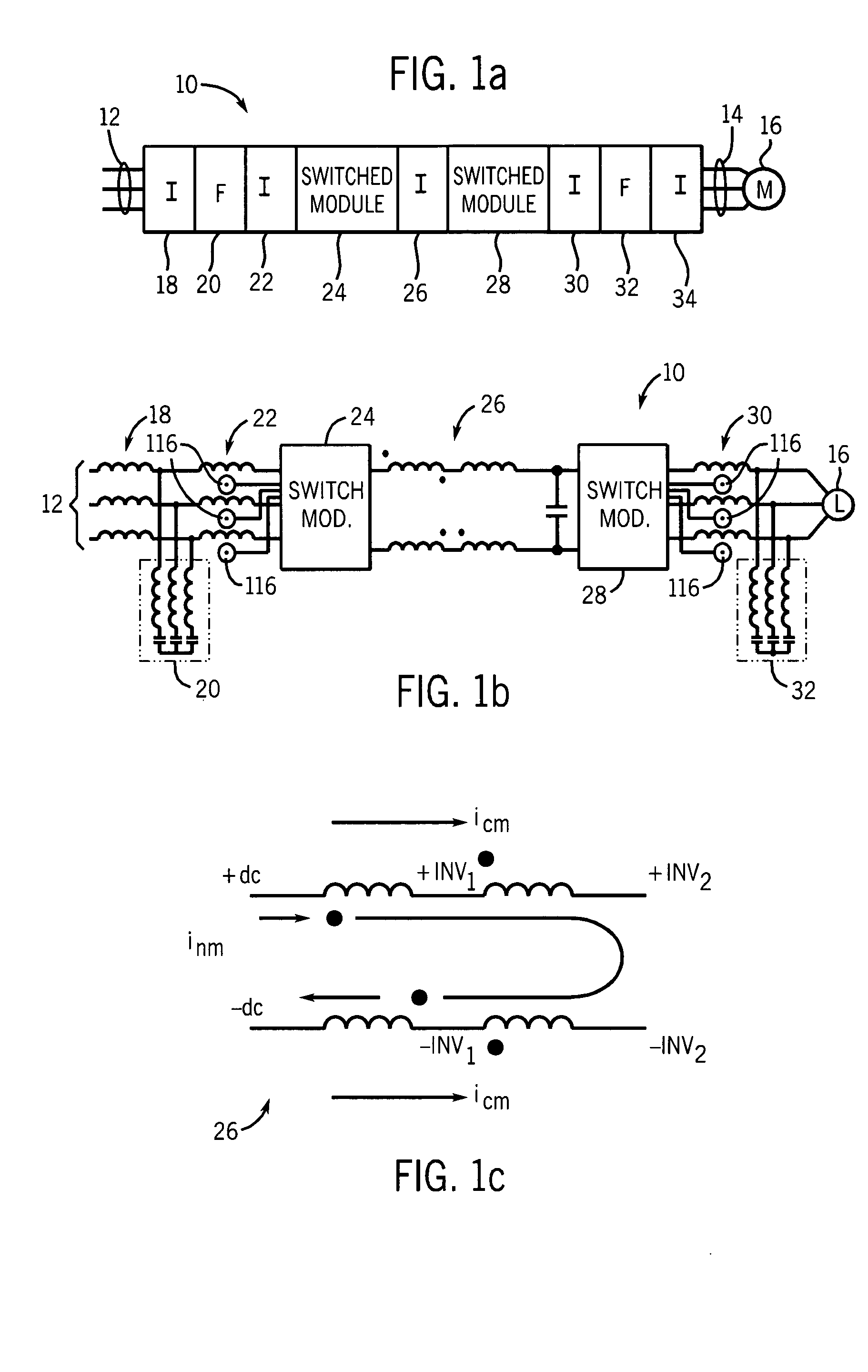
[0040] Turning now to the drawings, and referring first to FIG. 1a, a power converter circuit 10 is illustrated and designated generally by reference numeral 10. In the illustrated embodiment, circuit 10 receives input power, such as via three-phase conductors 12, and produces output power as illustrated at reference numeral 14 for application to a load, such as a motor 16. While reference is made in the present description to a power converter circuit generally, and including specific components, aspects of the present technique relating to configuration of modular inductors, incorporation of such components into systems, and overall system design can be employed in a wide range of circuits and settings. Thus, the present techniques apply equally well to universal power controllers, frequency controllers, micro-turbine generator applications, universal power sources, inverter circuits, matrix converters, by-directional and uni-directional power supplies, and so forth. In certain em...


PUM

PropertyMeasurementUnit
conductiveaaaaaaaaaa
surface areaaaaaaaaaaa
currentaaaaaaaaaa

Abstract

A modular inductor arrangement is provided in which a footprint of an enclosure for single or multiple phase inductors provides enhanced thermal transfer. The inductor coil may be wound about an axis generally parallel to a mounting surface of the package, so as to provide for reduced height and expanded footprint dimensions. The inductor package may be mounted on a thermal support, such as a fluid-cooled support. Heat is extracted from the assembly during operation, so as to establish a reduced maximum internal temperature as compared to here for known structures. The arrangement may be included in various circuit configurations, such as power converters. Other components may be incorporated and integrated into the package, including sensors, capacitor coils, other inductor coils, and so forth.

Description

BACKGROUND OF THE INVENTION [0001] The present invention relates generally to the field of power electronic devices such as those used in power conversion or to apply power to motors and similar loads. More particularly, the invention relates to an improved inductor arrangement which can be incorporated in a modular fashion in various circuits and which provides enhanced component integration and thermal characteristics. [0002] In the field of power electronic devices, a wide range of circuitry is known and currently available for converting, producing and applying power to loads. Depending upon the application, such circuitry may convert incoming power from one form to another as needed by the load. In a typical arrangement, for example, constant (or varying) frequency alternating current power (such as from a utility grid or generator) is converted to controlled frequency alternating current power to drive motors, and other loads. In this type of application, the frequency of the ...

Claims


Application Information

Patent Timeline
Patent Type & Authority Applications(United States)
IPC IPC(8): H01F17/04H01F27/02H01F27/04H01F30/12H01F37/00
CPCH01F17/045H01F27/027H01F37/00H01F30/12H01F27/04
Inventor SKIBINSKI, GARY LEONARD
Owner ROCKWELL AUTOMATION TECH
Why Eureka
Try Eureka